 Protection Testing Method Statement including testing procedures, relay settings, inspection, commissioning and safety checks for reliable electrical system protection.)
 Protection Testing Method Statement")
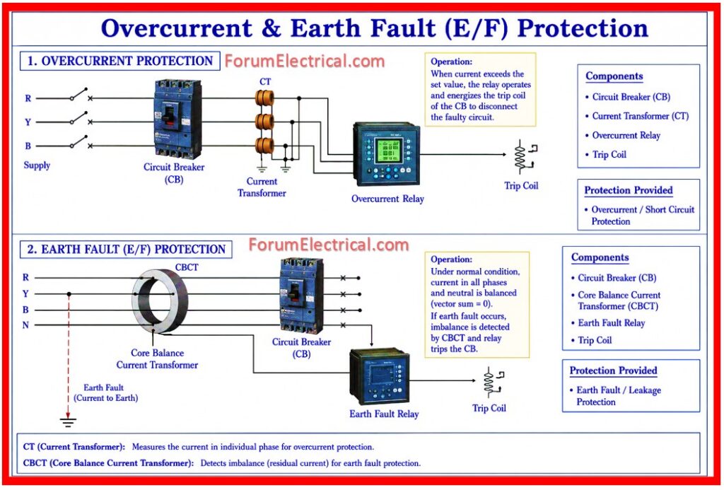
Overcurrent & Earth Fault (E/F) protection testing is carried out to verify the proper operation of protective relays against the overcurrent and earth fault conditions.
- Purpose
- Scope
- References
- Manpower
- Equipment Required
- Test Current Levels
- Safety Precautions and Measures
- Before Testing
- During Testing
- After Testing
- Procedure
- Visual Inspection
- Pre Testing Phase
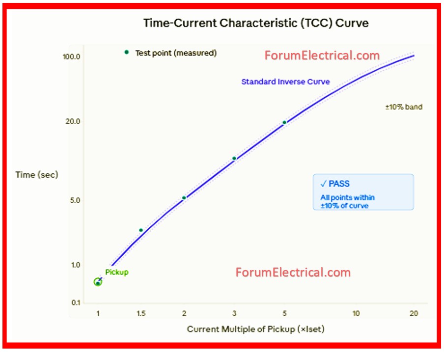
- Time Multiplier & TCC Curve Verification
- Overcurrent Protection Testing
- Earth Fault (E/F) Protection Testing
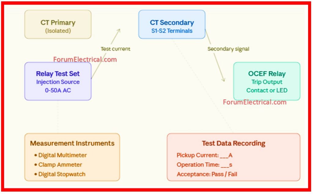
- OCEF Relay Testing
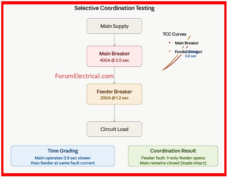
- Selective Coordination Testing
- Instantaneous/Definite Time Element Testing
- Current Transformer (CT) Testing & Verification
- Emergency Procedures
- Electrical Shock
- Equipment Failure
- Fire
- Records and Documentation
It ensures the relay detects faults accurately & trips the circuit breaker within the required time.
This testing used to improve electrical system safety, reliability and equipment protection.
Purpose
This Method statement defines the procedures, requirements and safety measures for conducting the testing of overcurrent and earth fault protection systems in electrical installations.
The testing assists in ensuring the reliability and accuracy of the protective devices and relays.
Scope
This procedure covers:
- Testing of overcurrent protection devices (circuit breakers, fuses and relays).
- Earth fault protection testing on every circuit.
- OCEF (Overcurrent & Earth Fault) relay calibration & verification.
- Time current characteristic (TCC) testing.
- Selective coordination testing between the protective devices.
References
IEC 60255-1: Electrical Relays: General Requirements.
IEC 61008: Residual Current Operated Circuit Breakers.
IEEE C37.48: Guide for the Phasor Measurement Unit (PMU) Testing and Calibration.
National Electrical Code (NEC): Article 230 & 240.
NFPA 70: National Electrical Code.
Manpower
| Position/Role | Qualifications |
| Test Supervisor | Senior Electrical Engineer with relay testing certification. |
| Test Technician | Certified electrical technician with 2+ years experience. |
| Safety Officer | OSHA certified with live work authorization. |
Equipment Required
- Portable relay test set (TRMS capable).
- Current injection transformer (or) testing adapter.
- Calibrated multimeter & clamp meter.
- Oscilloscope for the purpose of waveform analysis.
- Digital stopwatch that is used for the time measurement.
- Test leads & safety equipment.
Test Current Levels
| Test Type | Current Level | Expected Action |
| Below Pickup | < 90% Iset | No operation |
| At Pickup | 95-105% Iset | Trip within time delay |
| Instantaneous | > 110% Iset | Immediate trip |
Safety Precautions and Measures
Before Testing
- Carry out the lockout/tagout (LOTO) procedure on all associated circuits.
- Verify that all the equipment is deenergized using a voltage tester.
- Set up the barricades and also warning signs around the test area.
- Ensure a proper grounding of all test equipment.
During Testing
- Maintain a constant communication among team members.
- Never work alone – minimum two persons required.
- Wear the appropriate PPE (required): safety glasses, insulated gloves and hard hat.
- Keep the test leads clear & organized to avoid tripping hazards.
- Do not exceed safe current levels beyond equipment ratings.
After Testing
- Remove all test leads and equipment.
- Document all the findings and issues that are encountered.
- Provide a final report to the project manager within 24 hours.
Procedure
Visual Inspection
- Inspect the protective device for physical damage, corrosion (or) mechanical wear.
- Check the terminal connections for tightness and corrosion.
- Verify proper grounding of the all device casing.
- Confirm that the device is used to be properly mounted and secured.
- Check for any signs/indications of tampering, seal integrity & calibration lock status.
- Document all the visual findings with photographs if needed.
Pre Testing Phase
- Obtain the single line diagrams and protection scheme drawings.
- Verify the equipment nameplate ratings and protection settings.
- Perform visual inspection for any physical damage (or) tampering.
- Document all the necessary measurements and settings.
Time Multiplier & TCC Curve Verification
Verify the relay operation time at different current multiples (x) and confirm the TCC curve characteristics.
Procedure:
- Set the test equipment for any selected current level (e.g., 1.5x pickup).
- Measure & record the operation time using a digital stopwatch.
- Repeat for different current levels: 1.5x, 2x, 3x, 4x, 5x and 10x pickup.
- Plot the measured points on a semi log graph with the design of the TCC curve.
- Verify all the points fall within ±10% of the design curve.
- For inverse time relays verify the curve shape matches specified standard (IEC and ANSI).
- Document the time measurements on test form.
Overcurrent Protection Testing
- Primary Injection Testing: Inject test currents at 25%, 50%, 75%, 90%, 100%, and 110% of relay pickup settings.
- Record operation times and compare with TCC curves.
- Test instantaneous trip elements separately.
- Verify secondary injection testing for analog circuits using portable relay test sets.
Earth Fault (E/F) Protection Testing
- Inject earth fault currents at 10%, 25%, 50%, 75% and 100% of residual current rating.
- Record Earth Fault (E/F) relay operation times.
- Test both instantaneous & time delayed earth fault elements.
- Verify the zero sequence filtering & directional sensing if applicable.
OCEF Relay Testing
- Calibrate the OCEF relays using the certified test equipment.
- Test all the protection functions: instantaneous, definite time and inverse time.
- Connect the relay test set primary terminals to the CT secondary terminals.
- Set the relay test set to provide (attain) AC injection signal.
- Start with zero current (0) and gradually increase in 5% increments of the rated pickup current.
- Record the accurate current value when the relay indicates operation (visual light / audible signal).
- Repeat this method 3 times and then calculate average pickup current.
- Calculate error percentage: [(Actual – Design) / Design x 100].
- Acceptable error: ±5% of the design value.
- Verify the complete communication signals & logic blocks.
- Record all the test results with before/after the comparison.
Selective Coordination Testing
- Verify the proper time grading across protection devices in series.
- Confirm the minimum co-ordination time interval (typically 0.3 – 0.5 seconds).
- Validate the protection scheme selectivity as per single line diagram.
Instantaneous/Definite Time Element Testing
Verify quick acting protection elements that operate at the correct current threshold with minimal time delay.
Procedure:
- Set the test equipment to inject current below the instantaneous pickup threshold.
- Verify no operation of instantaneous elements.
- Increase current by 5% increments until the instantaneous element picks up.
- Record the pickup current value (typically 110% – 120% of primary instantaneous setting).
- Test at injection level 150% of instantaneous pickup & measure operation time.
- Operation time must be ≤50ms (approximately 2-3 cycles @ 50Hz).
- Repeat the testing minimum 3 times.
- Verify the trip output energizes correctly (contacts change state and LED illuminates).
Current Transformer (CT) Testing & Verification
CT Polarity Verification
- Inject AC current into the CT primary (10) winding.
- Using an oscilloscope , verify secondary (20) current is in phase with the primary.
- Mark the CT terminals with polarity indicators if not already marked.
- Document polarity verification result.
CT Ratio Verification
- Inject known current into the primary winding.
- Measure the secondary (20) current using a calibrated clamp ammeter.
- Calculate the actual CT ratio: Primary Current (10) / Secondary (20) Current.
- Compare with the nameplate ratio.
- Acceptable error: ±1% of nameplate ratio.
CT Insulation Resistance
- Disconnect CT from the electrical circuits.
- Using the megohmmeter at 1000VDC measures insulation resistance.
- Primary-to-secondary insulation: Minimum 10 MΩ.
- Primary-to-earth: Minimum 5 MΩ.
- Secondary-to-earth: Minimum 5 MΩ.
Emergency Procedures
Electrical Shock
- Remove victim from the electrical contact source.
- Call the emergency services.
- Perform CPR if trained & victim is unresponsive.
- Do not move the victim unless in immediate danger.
Equipment Failure
- Stop all the testing immediately.
- Deenergize test circuit.
- Notify the supervisor and tag equipment as out of service.
- Schedule the equipment repair before resuming work.
Fire
- Evacuate the area immediately.
- Use the fire extinguisher only if fire is small & controllable.
- Call the emergency services.
- Account for all the personnel.
Records and Documentation
All test records must include:
- Equipment identification and their serial numbers.
- Test date, time and personnel names.
- All the measured values and calculated results.
- Compliance with the specification limits.
- Supervisor approval & sign-off.
- Any deviations (or) non-conformances noted.
- Test the equipment calibration certificates.