Selecting the correct cable size for a diesel (or) gas generator is one of the most important factors in any electrical installation.
- Understanding Generator KVA Rating
- Why Correct Cable Sizing Important?
- How to Calculate Cable Size for a Generator?
- Key Factors affecting Cable Size Selection
- Generator KVA to Cable Size Chart
- Cable Sizing for Long Cable Runs
- Standards and Codes for Generator Cable Sizing
- Common Mistakes to Avoid
- Conclusion
An undersized cable can overheat that cause voltage drop, damage connected equipment and create a serious fire hazard while an oversized cable adds unnecessary cost.
This post provides a practical generator KVA to cable size chart which explains the formulas utilized to calculate current and cable size and explain through the key factors that influence correct cable selection for the generators ranging from small 15 KVA units to large 1000 KVA industrial generators.
Understanding Generator KVA Rating
KVA (or) kilovolt-ampere is the unit used to express the apparent power output of a generator.
Unlike kilowatts (KW) which measure real power actually that is converted into usable work that KVA is for both real and reactive power in the electrical system.
The relationship between KVA and KW depends on the power factor of the connected load that is commonly assumed to be 0.8 for standard generator applications.
A generators KVA rating along with its voltage and power factor (PF) determines the full load current (FLC) that the cable connecting the generator to the distribution panel should safely carry.
Why Correct Cable Sizing Important?
Prevents Overheating
Undersized cables carrying current beyond their rated capacity heat up, degrading insulation and creating fire risk.
Minimizes Voltage Drop
Long cable runs with inadequate cross-sectional area cause voltage drop that is reducing equipment performance and efficiency.
Ensures Safety Compliance
Properly sized cables meet national and international electrical codes, protecting personnel and property.
Improves System Reliability
Correctly rated cables reduce nuisance tripping of protective devices and extend equipment life.
Optimizes Cost
Right sizing avoids the unnecessary expense of an oversized conductor while still meeting safety margins.
How to Calculate Cable Size for a Generator?
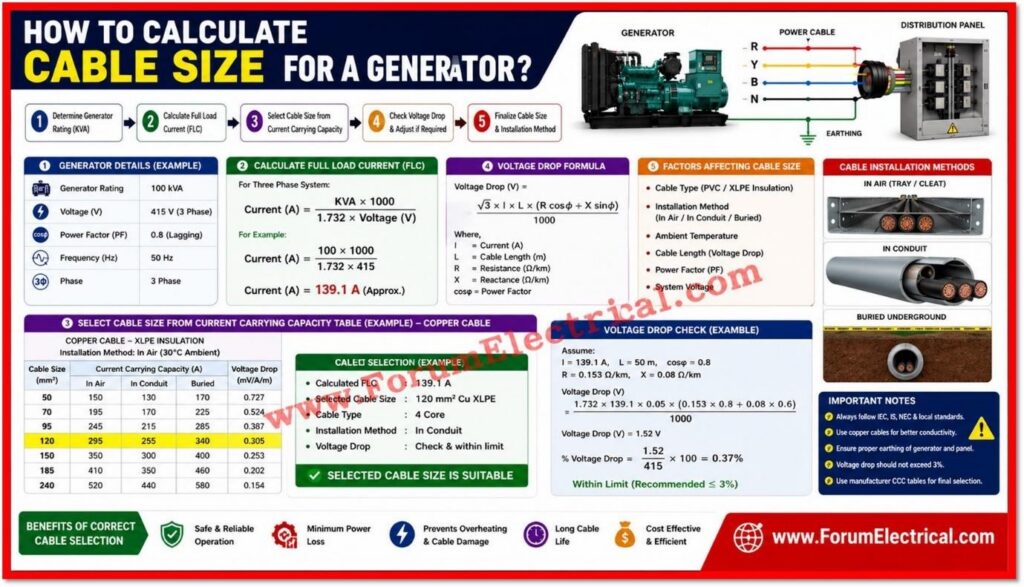
The first step in selecting a cable is calculating the generators full load current (FLC) using the standard three phase power formula:
Current (A) = (KVA x 1000) / (1.732 x Voltage)
For a 415V three phase system this formula gives the approximate full load amperage the generator will supply.
Once the full load current (FLC) is known the cable size is selected from manufacturer current carrying capacity tables factoring in the cable type (PVC or XLPE insulation), installation method (in air, in conduit or buried underground), ambient temperature and the length of the cable run since voltage drop becomes more significant over the longer distances.
Key Factors affecting Cable Size Selection
Ambient Temperature
Higher ambient temperatures reduce a cables current-carrying capacity that is requiring a larger conductor (or) a derating factor.
Installation Method
Cables installed in conduit, buried underground (or) run in free air each have different heat dissipation characteristics & derating factors.
Cable Length & Voltage Drop
Longer cable runs need larger conductors to keep voltage drop within acceptable limits which is typically below 3% to 5%.
Grouping of Cables
Multiple cables bundled together generate more combined heat & may require an additional derating factor.
Cable Insulation Type
XLPE-insulated cables generally have a higher current rating than PVC insulated cables of the same size.
Type of Load
Motor loads, UPS systems and other non linear loads may need additional margin due to inrush current (or) harmonics.
Generator KVA to Cable Size Chart
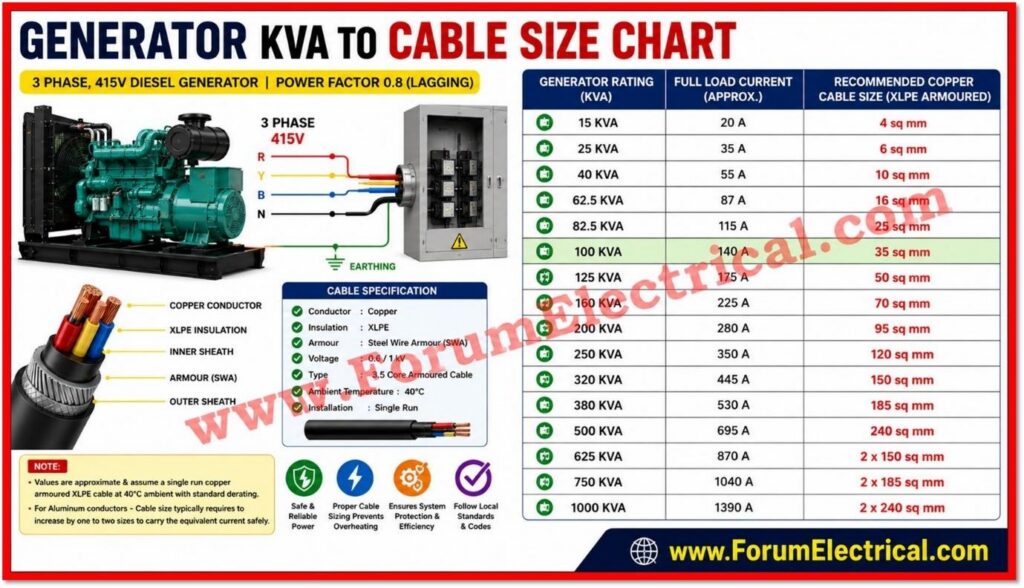
The following chart provides commonly utilized cable size recommendations for standard 3 phase, 415V diesel generators based on an assumed power factor of 0.8, XLPE-insulated armored copper cable and standard ambient conditions.
This chart is intended as a general reference
Note: Always verify with a qualified electrical engineer and local cable manufacturer current rating tables before finalizing a project.
| Generator Rating (KVA) | Full Load Current (Approx.) | Recommended Copper Cable Size |
| 15 KVA | 20 A | 4 sq mm |
| 25 KVA | 35 A | 6 sq mm |
| 40 KVA | 55 A | 10 sq mm |
| 62.5 KVA | 87 A | 16 sq mm |
| 82.5 KVA | 115 A | 25 sq mm |
| 100 KVA | 140 A | 35 sq mm |
| 125 KVA | 175 A | 50 sq mm |
| 160 KVA | 225 A | 70 sq mm |
| 200 KVA | 280 A | 95 sq mm |
| 250 KVA | 350 A | 120 sq mm |
| 320 KVA | 445 A | 150 sq mm |
| 380 KVA | 530 A | 185 sq mm |
| 500 KVA | 695 A | 240 sq mm |
| 625 KVA | 870 A | 2 x 150 sq mm |
| 750 KVA | 1040 A | 2 x 185 sq mm |
| 1000 KVA | 1390 A | 2 x 240 sq mm |
Note: Values are approximate & assume a single run copper armoured XLPE cable at 40°C ambient with standard derating.
For Aluminum conductors – Cable size typically requires to increase by one to two sizes to carry the equivalent current safely.
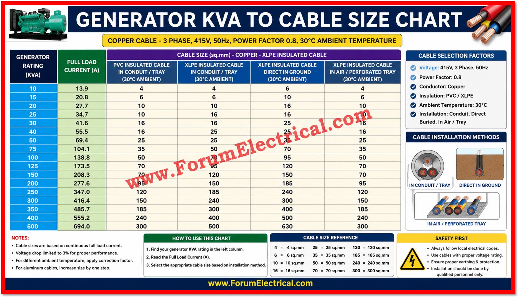
Cable Selection Factors: Different Conditions
- Copper Cable
- 3 Phase
- 415 V
- 50 Hz
- Power Factor: 0.8
- Ambient Temperature: 30°C
| Generator Rating (kVA) | Full Load Current (A) | PVC Insulated Cable in Conduit / Tray (30°C) | XLPE Insulated Cable in Conduit / Tray (30°C) | XLPE Insulated Cable Direct in Ground (30°C) | XLPE Insulated Cable in Air / Perforated Tray (30°C) |
|---|---|---|---|---|---|
| 10 | 13.9 | 4 | 4 | 6 | 4 |
| 15 | 20.8 | 6 | 6 | 10 | 6 |
| 20 | 27.7 | 10 | 10 | 16 | 10 |
| 25 | 34.7 | 10 | 16 | 16 | 10 |
| 30 | 41.6 | 16 | 16 | 25 | 16 |
| 40 | 55.5 | 16 | 25 | 25 | 16 |
| 50 | 69.4 | 25 | 25 | 35 | 25 |
| 75 | 104.1 | 35 | 50 | 70 | 35 |
| 100 | 138.8 | 50 | 70 | 95 | 50 |
| 125 | 173.5 | 70 | 95 | 120 | 70 |
| 150 | 208.3 | 70 | 120 | 150 | 70 |
| 200 | 277.6 | 95 | 150 | 185 | 95 |
| 250 | 347.0 | 120 | 185 | 240 | 120 |
| 300 | 416.4 | 150 | 240 | 300 | 150 |
| 350 | 485.7 | 185 | 300 | 400 | 185 |
| 400 | 555.2 | 240 | 400 | 500 | 240 |
| 500 | 694.0 | 300 | 500 | 630 | 300 |
Cable Sizing for Long Cable Runs
When the distance between the generator and the distribution panel exceeds approximately 30 to 50 meters voltage drop becomes a critical factor that can outweigh the current carrying capacity requirement alone.
In such conditions the cable size determined by ampacity tables may require to be increased to keep the voltage drop within the recommended 3% to 5% limit.
Voltage drop can be calculated using the formula:
Voltage Drop (V) = (1.732 x Current x Length x Resistance per km) / 1000
Where
Resistance values are obtained from the cable manufacturers technical datasheet.
For critical (or) long distance installations running parallel cable runs is often more economical than using a single very large conductor.
Standards and Codes for Generator Cable Sizing
Cable sizing for generators must always follow recognized standards to ensure safety and compliance.
Common references include
• IS 1255 and IS 7098 in India,
• BS 7671 (IET Wiring Regulations) in the United Kingdom,
• National Electrical Code (NEC) Article 445 in the United States and
• IEC 60364 internationally.
These standards define minimum cable ampacity, derating factors, earthing requirements and protective device coordination for generator installations.
Common Mistakes to Avoid
- Sizing the cables based on generator KVA rating alone without considering for cable length & voltage drop.
- Ignoring an ambient temperature derating factors in hot climates (or) enclosed generator rooms.
- Failing to account for cable grouping when multiple circuits run together in the same tray (or) conduit.
- Using aluminium cable sizing charts interchangeably with copper cable charts without any adjustment.
- Overlooking the requirement for a properly and accurately sized neutral & earth conductor alongside the phase conductors.
Conclusion
Choosing the correct appropriate cable size for a generator installation is important for safety, performance & long term reliability.
While the generator KVA to cable size chart in this post provides a practical starting point for common ratings from 15 KVA to 1000 KVA actual cable selection must always factor in cable length, ambient conditions, installation method & applicable local electrical codes.
Consulting a qualified electrical engineer & referring to the cable manufacturers current rating tables ensures that the final installation is both code compliant & safe for continuous operation.

