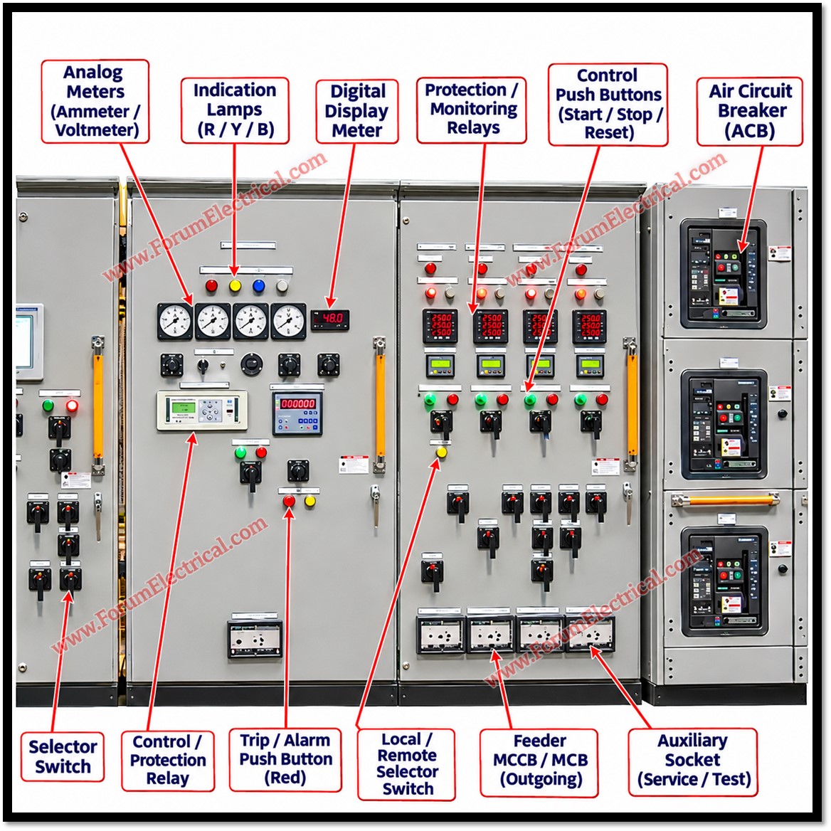
Pre-commissioning confirms that a Main Distribution Board (MDB) (or) Motor Control Centre (MCC) is correctly built, safe, protected and functional before first energization.
Under IEC 61439, verification has two parts:
- Design verification (type testing by the manufacturer) and
- Routine verification (applied to every assembly, in the factory and on site).
Purpose
Site checks prove that transport and installation caused no damage and that the assembly matches the approved design.
Installation alone does not make a panel ready for energization.
Responsibility
Supervisor: The supervisor ensures inspections and tests are completed, recorded and reviewed, and that sensitive electronics, SPDs and VFDs are isolated before IR testing at specified test voltages and per manufacturer instructions.
Authorization must rest on documented evidence, not on installation completion.
Relevant Standards
| Standard | Relevance |
|---|---|
| IEC 61439-1 / -2 | LV switchgear and controlgear assemblies; design and routine verification (Clause 11) |
| IEC 60947-1, -2, -4-1 | LV breakers (ACB/MCCB), contactors and motor starters |
| IEC 60364-6 / 5-54 | Initial verification, insulation resistance, earthing and protective conductors |
| IEC 60529 | Degrees of protection (IP code) |
| IEC 61869-2 | Current transformers: ratio, polarity, accuracy class |
| IEC 60255 series | Measuring relays and protection equipment |
| IEC 60909 | Short-circuit current calculation for rating and coordination |
| IEC 60204-1 | Electrical equipment of machines; emergency stop and stop categories |
| IEC 61800-5-1 | Adjustable speed drives (VFD) safety requirements |
| IEC 61131-3 | PLC programming languages |
| IEEE Std 43 | Insulation resistance testing of rotating machinery |
| IEEE Std 242 (Buff Book) | Protection and coordination of industrial power systems |
| ANSI/NETA ATS | Acceptance testing specifications for electrical power equipment |
| NFPA 70E | Electrical safety in the workplace; LOTO and energization practices |
Visual Inspection
Work starts with approved SLDs, GA drawings, schematics and equipment tags.
The as-installed panel must match the latest approved revision; tag or drawing mismatches are a common cause of wrong-feeder operation. Alignment and anchoring matter mechanically: twisted (or) poorly anchored shipping sections strain busbar joints and obstruct draw-out breaker racking.
The enclosure IP rating (IEC 60529) holds only if gaskets, doors and gland plates are intact and cable entries are sealed.
Equipment ratings, working clearances and access space are checked against drawings, while internal clearances and creepage distances follow IEC 61439-1.
Busbar and Power Circuits
- Busbars: inspect supports and insulation for cracks, since damaged supports reduce short-circuit withstand. Confirm L1-L2-L3 identification is consistent throughout and verify phase sequence with a phase-rotation meter, as it determines motor direction.
- Joints: tighten to the manufacturer’s torque values with a calibrated wrench and mark with torque paint. Loose joints cause high resistance and overheating.
- Cables: verify size against design current, derating and fault duty; check correct lugs, crimping, glands and armour earthing, and that terminations carry no mechanical strain.
- CTs: verify ratio, polarity, accuracy class and burden (IEC 61869-2). A live CT secondary must never be open-circuited because it can develop dangerously high voltage; keep it shorted until connected, with a single earth point.
Breakers and Protection
ACB and MCCB ratings (In, Icu/Ics, Icw per IEC 60947-2) must exceed the prospective fault level from the short-circuit study (IEC 60909).
Mechanical checks include racking in and out, shutters, spring charging, indicators and key interlocks.
Electrical checks cover shunt-trip, closing and undervoltage circuits, anti-pump logic, auxiliary contacts and interlocks, especially incomer and bus-tie interlocks that prevent unintended paralleling of sources.
Relay and trip-unit settings (long-time, short-time, instantaneous, earth-fault) are compared with the approved coordination study, and as-set values are recorded.
Secondary injection proves relay (or) trip-unit pickup and timing; primary injection proves the complete chain from CT through relay to breaker trip.
Electrical Pre-Commissioning Tests
- Insulation resistance: IEC 60364-6 specifies 500 V DC and a minimum of 1 MΩ for circuits up to 500 V, and 250 V DC and 0.5 MΩ for SELV/PELV. Project specifications or ANSI/NETA ATS may require higher voltages or values; the approved specification and manufacturer instructions govern. Test phase-to-phase and phase-to-earth, discharge circuits afterwards, and record temperature and humidity.
- Isolation of sensitive devices: disconnect or isolate SPDs, VFDs, electronic meters, PLC modules and capacitors before testing, as the test voltage can damage them.
- Contact resistance: measure breaker main contacts with a micro-ohmmeter and compare poles with each other and with factory data; high readings indicate contamination or wear.
- Breaker timing: measure opening and closing times where specified, against manufacturer limits.
- CT and injection tests: confirm ratio and polarity, and where required knee-point and loop resistance.
- Continuity: confirm protective-circuit continuity between the PE bar and exposed conductive parts (IEC 61439-1, Clause 11), and control-circuit continuity.
Record every result against approved acceptance criteria on signed, witnessed test sheets.
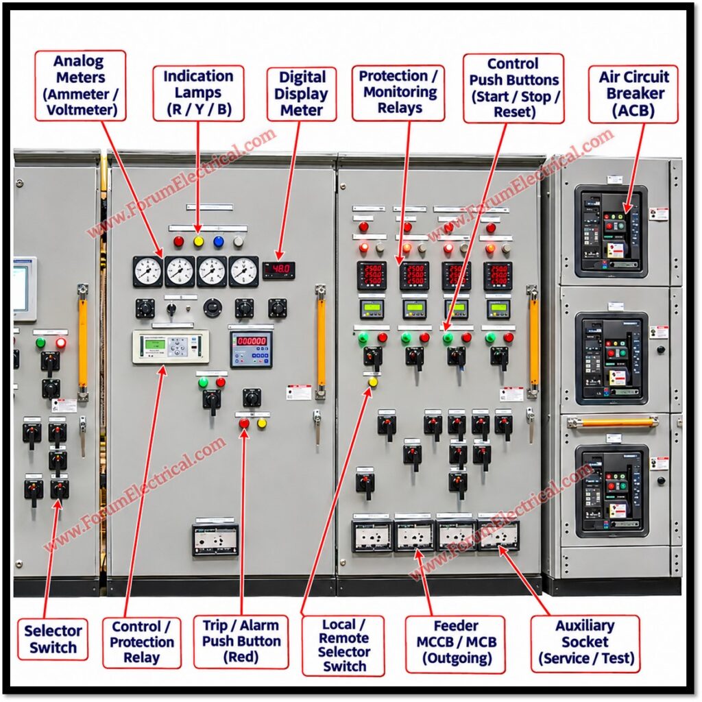
MCC and Motor Feeders
Verify DOL, star-delta and VFD feeder wiring against schematics.
For star-delta, confirm timer settings and the interlock preventing star and delta contactors closing together which would cause a phase-to-phase fault. Contactors and starters follow IEC 60947-4-1 utilization categories (e.g., AC-3).
Set overload relays to the motor nameplate full-load current and verify thermistor and earth-fault protection.
VFD parameters (motor data, ramps, limits) must match the motor, and drives follow IEC 61800-5-1; observe the capacitor discharge time before touching terminals.
Test Local/Remote selection, Start/Stop and hardwired emergency-stop circuits against IEC 60204-1 stop categories.
Motor winding insulation is assessed per IEEE 43, with the cable disconnected from the VFD.
Confirm rotation during an approved functional test, preferably with the motor uncoupled, to avoid damaging pumps or fans.
Control, PLC and SCADA
Verify control supply voltage and polarity, wiring and I/O connections.
Perform point-to-point checks of digital and analogue signals from field to PLC to SCADA, including 4-20 mA scaling and alarm limits.
Confirm breaker status, trip feedback, alarms and remote commands operate correctly, and that communications (e.g., Modbus, Profibus, Ethernet) are healthy.
Cause-and-effect logic is tested against the approved matrix and PLC logic per IEC 61131-3 practice.
Final Pre-Energization Checks
Before energization, complete approved ITPs, check sheets and test reports, and close or formally accept punch-list items; safety-critical items must be closed.
Confirm earthing, covers, barriers, shutters and cable entries are in place, and remove test leads, temporary earths and tools.
Verify protection settings and PTW/LOTO clearance (NFPA 70E principles), then obtain written authorization.
Good practice is to energize incomer first, then the busbar, then outgoing feeders one at a time, with thermographic inspection under load.

