
Power distribution networks depend on electrical substations which rarely notify their potential faults.
- Why Preventive Maintenance is Essential?
- 7-Step Preventive Maintenance Procedure
- Step-1: Visual Inspection
- Step-2: Transformer Oil/Insulation Health Check
- Step-3: DC System & Battery Backup Verification
- Step-4: Circuit Breaker & Protection Relay Testing
- Step-5: Grounding & Earthing System Measurement
- Step-6: Thermal Scanning & Load Optimization
- Step-7: Documentation
- Advantages of Preventive Maintenance
- Summary
- Checklist
They gradually deteriorate through
- Oil deterioration,
- Contact wear,
- Insulation failure and
- Thermal stress
- Until an essential component malfunctions.
By then, the damage goes beyond a single component.
Systematic preventative maintenance prevents catastrophic failures not reactive repairs.
This method of operation transforms insecure substations into reliable power distribution systems using a validated seven-step procedure.
Why Preventive Maintenance is Essential?
Any unexpected substation outage affects the entire power grid.
Production stops, commercial facilities lose money and key infrastructure fails.
Equipment breakdowns during fault circumstances pose substantial safety risks for maintenance workers and surrounding facilities.
These dangers are avoided by preventive maintenance.
It detects degradation early when correction is easy and cheap.
More significantly it sets a baseline of equipment health to help maintenance teams predict breakdowns.
7-Step Preventive Maintenance Procedure
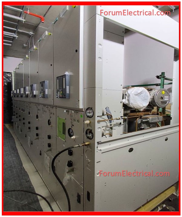
Step-1: Visual Inspection
Visual inspections indicate equipment status before advanced testing equipment is used.
Experienced maintenance workers can spot faults by analyzing bodily signs before electrical degeneration.
Check transformer gaskets and bushings for oil weepage as you walk through the substation.
Discoloration or melting insulation indicate overheating in circuit breakers and isolators.
In coastal (or) industrial areas where atmospheric contamination promotes deterioration, check busbars & connections for corrosion.
Check control panels for loose hardware, frayed wire and moisture.
Most major failures have apparent warning indicators before system alerts.
A discolored contact surface, corroded terminal (or) concrete oil stain tell a narrative about equipment health that numbers cannot.
Prior to alerts, 70-80% of major failures have visible faults.

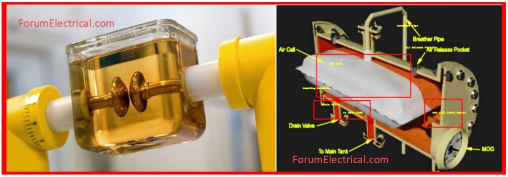
Step-2: Transformer Oil/Insulation Health Check
Transformer oil serves as both an insulator and a coolant.
Moisture intrusion, temperature stress, & electrical stress all deteriorate the dielectric characteristics over time.
This degeneration doesn’t reveal itself with evident signs until insulation fails frequently with catastrophic implications.
Dissolved Gas Analysis (DGA) detects distinctive gases created by electrical and thermal stress providing an early warning of internal defects.
Different gas combinations signal distinct problems:
- Arcing produces acetylene,
- Overheating produces ethylene and methane and
- Partial discharge produces hydrogen.
Regular DGA testing changes transformer maintenance from reactive to predictive.
The Breakdown Voltage (BDV) test determines the oil’s capacity to tolerate electrical stress.
A BDV number more than 30 kV indicates appropriate dielectric strength however lower values require quick care via oil filtering (or) total oil replacement.
This basic test avoids dielectric failures which could damage transformers.
Step-3: DC System & Battery Backup Verification
Normal Operation
- During normal operation, the DC supply system runs in the background, hardly drawing attention to itself.
Fault Conditions
- However during fault conditions if the AC system may be affected, the DC supply is an essential infrastructure.
- It powers protection relays supplies closing energy to circuit breakers and also assures that fault isolation works as intended.
- A thorough DC system testing checks at battery charger operation ensures adequate float voltage across battery cells and checks electrolyte levels in flooded lead-acid batteries and evaluates inter-cell connection resistance.
- Each cell in a lead-acid battery should sustain about 2.2 volts under float circumstances.
- Significant variations signal cell breakdown which threatens the entire battery bank.
- A failed DC supply during a fault condition might disable circuit breakers allowing fault current to flow unchecked across the system.
This cascading failure condition increases a minor malfunction into a significant system disruption resulting in extensive equipment damage.
Step-4: Circuit Breaker & Protection Relay Testing
Circuit breakers are the mechanical basis of substation protection systems.
They must function reliably after months (or) years of inactivity interrupting fault currents that can surpass normal operating current.
This severe duty cycle necessitates regular mechanical & electrical performance checks.
Contact Resistance Measurement
Contact resistance measurement displays the state of the breaker contacts that carry load current throughout normal operation.
High contact resistance generates heat which accelerates wear and can prevent effective current interruption under fault conditions.
Target contact resistance for high-voltage circuit breakers should be less than 100 microohms.
Timing Tests
Timing tests confirm that the breaker’s operating speed remains within manufacturer limits.
Protection relays are functionally tested to ensure appropriate operation and cooperation with other protective devices in the system.
Each component that fails during testing reflects the potential system outage that the preventative maintenance has successfully avoided.

Step-5: Grounding & Earthing System Measurement
Proper grounding is the foundation of an electrical safety across the substation.
During fault conditions grounding systems must properly dissipate fault current to earth while keeping contact and step potentials to safe limits.
Over time, soil conditions change, corrosion attacks ground connections and ground resistance rises.
Important substations that manage significant fault currents must have ground resistance less than 1 ohm (1 Ω) although conventional substations normally aim for values less than 5 ohms (5 Ω).
| Substation Type | Recommended Earth Resistance |
| Major HV/EHV | < 1 Ω |
| Standard MV/LV | < 5 Ω |
Regular measurements with ground resistance testing equipment detect deterioration before it becomes a safety problem.
Poor grounding escalates minor defects into serious safety failures where equipment cases & structural steel might reach dangerous levels.
Step-6: Thermal Scanning & Load Optimization
Infrared thermography identifies faults that could have remained undetected.
Loose connections cause heat due to increased resistance.
Phase mismatches cause uneven heating patterns & overloaded components exceed their thermal design limits.
All of these conditions are easily visible in thermal imaging before they cause device failure.
A full thermal survey looks at
- Electrical joints,
- Current transformers,
- Busbars,
- Circuit breakers, and
- Cable terminations.
Hotspots that reach 80°C require rapid inspection and corrective action.
To lower peak loads simple techniques like as connection tightening, load rebalancing between phases (or) changing the operation schedule are frequently used.
Regular thermal scanning converts maintenance from a reactive activity to predictive asset management.
Equipment does not fail unexpectedly it gives thermal warning indications for weeks (or) months prior to deterioration reaches levels that are essential.
Step-7: Documentation
Documenting and analyzing maintenance data makes it useful.
Log inspections, tests and corrective actions with dates, equipment identification, measured values and equipment condition observations.
The value of documentation comes from comparing current readings to previous performance.
Slowly rising contact resistance, oil breakdown voltage or thermal signatures indicate equipment deterioration and anticipate future failures.
This analysis lets repair be scheduled during planned outages rather than emergency breakdowns.
Modern asset management systems alert when trending shows maintenance thresholds.
The predictive maintenance maximizes equipment availability and reduces maintenance expenses.
Advantages of Preventive Maintenance
Systematic maintenance eliminates unplanned outages that interrupt operations and protects expensive equipment expenditures assures worker safety maintains regulatory compliance & reduces emergency repair costs.
Success requires equipment priority-based maintenance scheduling, skilled staff with the correct skills and materials and computerized systems to track equipment history & predict future requirements.
Summary
Overall, substations fail predictably.
- Deterioration,
- Oil contamination,
- Overheating and
- Performance fluctuations
- Indicate equipment failure.
Preventive maintenance detects faults early for affordable maintenance. Failures cause reactive maintenance which is costly and damaging.
Power-dependent organizations need constant infrastructure maintenance. Maintenance now prevents outages forthcoming.
This is about whether you can afford important equipment failure during peak demand not preventive maintenance.