. To ensure safe and dependable switchgear operation include pre-commissioning inspections, insulation tests, dielectric tests, CT/VT verification, relay testing, interlock checks and SCADA integration.)
 Testing & Commissioning Step-by-Step Procedure")
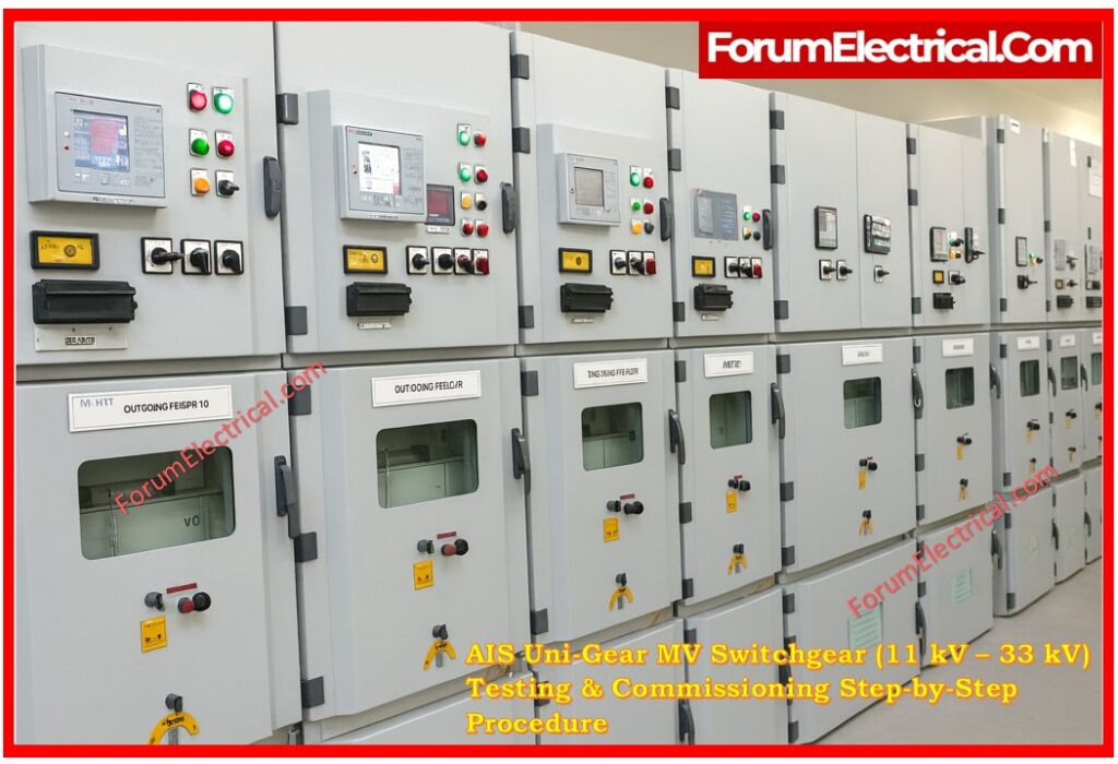
Air-Insulated Switchgear (AIS) Uni-Gear systems with voltage ratings ranging from 11 kV to 33 kV are necessary in
1). Distribution substations,
2). Industrial networks and
3). Utility applications.
Systematic testing and commissioning are required to ensure their safe and reliable performance.
Before the switchgear is turned ON this procedure checks for
- Equipment integrity,
- Insulation health,
- Protection coordination,
- Interlocking mechanisms & communication readiness.
This post outlines the whole sequence of tests needed to commission MV AIS Uni-Gear switchgear in accordance with industry standards (IEC/IEEE).
Pre-Commissioning Inspection
Before conducting electrical tests a comprehensive visual and mechanical check is required.
Engineers should ensure that all panels are clean, debris-free and appropriately labeled.
CT & PT ratios must match the approved designs and coordination studies.
Mechanical integrity inspections guarantee that busbar chambers, shutters, isolators, earthing switches and enclosure doors function properly.
Grounding connections, including frame and busbar earthing should be checked for continuity and correct torque.
Mechanical interlocks such as racking interlocks, earthing switch interlocks and door interlocks must also be tested for proper operation.
Electrical Testing
Insulation Resistance (IR) Test
Insulation resistance testing checks the dielectric properties of busbars, cables, & control wire.
To test MV busbars and power lines utilize a 5 kV DC megger with an IR value that exceeds 1 GΩ.
Control wiring is tested at 500 V DC, with permissible values exceeding 10 MΩ.
Low readings could indicate moisture intrusion, contamination or broken insulation.
High Voltage (Dielectric) Test
Dielectric resist testing confirms that the insulation system can survive overvoltage during operation.
Depending on the switchgear’s rated voltage an AC test voltage of 28 kV to 50 kV is supplied across busbars & power circuits.
The equipment must sustain the test duration without flashover (or) partial discharge that exceeds permitted limits.
Contact Resistance Test
The resistance across the main contacts of a circuit breaker is measured using a microohmmeter.
Values below 100 µΩ suggest healthy & low-loss contact surfaces.
Excessive resistance could indicate oxidation, pitting, misalignment (or) incorrect contact pressure.
CT/VT Testing
Instrument transformers are tested for ratio accuracy, polarity and phase displacement.
CT primary injection ensures the correct secondary output and polarity marking assuring proper relay operation.
Ratio verification and insulation checks are also part of VT tests.
Any departure from the expected values should be corrected before the system is fully operational.
Protection Relay Testing
Primary Injection Testing
Primary injection tests the whole operation of the protection chain which includes CTs, wire, relays and tripping circuits.
A full-primary current is delivered into the circuit to test the CT ratio, polarity, burden and relay operation under true primary conditions.
This test is required to check that no wiring faults, polarity mismatches (or) CT saturation concerns exist.
Secondary Injection Testing
Secondary injection replicates the necessary current and voltage at the relay terminals to evaluate protective logic.
- Overcurrent (OC),
- Earth fault (EF),
- Overvoltage,
- Undervoltage and
- Directional protection
are all tested.
Relay pickup, timing and tripping are validated using the coordination study.
All relay settings including IDMT curves, instantaneous trips, earth fault thresholds and directed elements must be correspond to the protection coordination report.
Trip outputs must be properly mapped to breaker trip coils & alarms must be routed to the annunciation (or) SCADA system.
Functional and Interlock Testing
All mechanical and electrical interlocks should operate properly to ensure operator safety and avoid improper switching sequences.
Racking mechanisms are evaluated to make sure that proper movement between test, service and isolated positions.
Key interlocks are tested to make sure that breakers and earthing switches cannot be triggered in unsafe conditions.
Local and remote CLOSE/TRIP commands are checked to ensure breaker functionality and auxiliary contact feedback.
SCADA and Automation Testing
If the switchgear is connected to SCADA (or) substation automation, communication protocols like IEC 61850, Modbus (or) DNP3 must be established and approved.
- Breaker status indications,
- Remote OPEN/CLOSE instructions,
- Analog values (current, voltage and power),
- Protection alarms,
- Marshalling logic,
and if appropriate, GOOSE messaging are all tested.
Network redundancy and time synchronization (SNTP/PTP) must also be verified.
Conclusion
Testing and commissioning AIS Uni-Gear MV switchgear is an organized and essential procedure that ensures system dependability, operator safety and adherence to engineering specifications.
Each step from the pre-commissioning inspection to SCADA integration is important in identifying the faults prior to energization.
Proper implementation of these tests reduces failures and also increases the equipment life and guarantees that the switchgear runs smoothly within the power network.