
What is the meaning of an ideal transformer?
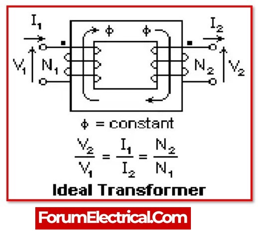
An ideal transformer is one that does not have any losses, such as copper and core. In this transformer, the output and input powers are equivalent. This transformer’s efficiency is 100 percent, hence there is no power loss within the transformer.
Ideal Transformer’s Working Principle:
An ideal transformer operates according to two principles, such as when an electric current generates a magnetic field and a changing magnetic field in a coil induces a voltage across the ends of the coil. The magnetic flux is generated when the current in the primary coil is altered. Changing magnetic fields can therefore create a voltage in the secondary coil.
When current runs through the primary coil, it produces a magnetic field. The two windings are wrapped in the vicinity of a very strong magnetic core, such as iron, so the magnetic flux flows through them. Once a load has been connected to the secondary coil, the voltage and current will flow in the direction specified.
Properties of Ideal Transformer:
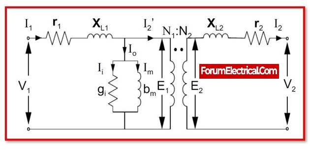
An ideal transformer is a theoretical transformer with the following properties:
- The resistance of the primary and secondary windings is negligible or zero.
- There is no flux leakage, therefore the entire flux is contained within the magnetic circuit.
- Due to the infinite permeability of the magnetic core, negligible mmf is required to establish flux in the core.
- No losses are caused by winding resistance, hysteresis, or eddy currents. Thus, the efficiency is 100 percent.
Equation for an Ideal Transformer:
The output power is equal to the input power in an ideal type transformer. As a result, there is no loss of power.
E2 x I2 x Cos ø = E1 x I1 x Cos ø
or
E2 x I2 = E1 x I1
From the above equation,
E2/E1 = I2/I1
As a result, the conversion ratio equation is as follows.
E2/E1 = N2/N1 = I1/I2 = K
Primary and secondary currents are inversely proportional to their twists.
Ideal Transformer Phasor Diagram:
Ideal transformer’s phasor diagram with no load is given below:
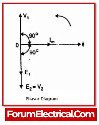
When the transformer is not in use, the current within the secondary coil can be zero, resulting in I2 = 0.
In the diagram above,
- “V1” is the input supply voltage.
- E1 is an induced e.m.f.
- ‘I1’ is the primary current.
- ‘ø’ stands for Mutual flux.
- “V2” is the secondary output voltage.
- ‘E2’ represents the secondary induced e.m.f.
When the transformer windings have no resistance, the induced voltage ‘E1’ within the main winding is equal to the applied voltage ‘V1’. However, according to Lenz’s law, the main winding E1 is equivalent and reverse to the primary voltage ‘V1’. The primary current that draws the supply can be sufficient to produce an alternating flux ” within the core.
As a result, both the main current and the alternating flux are in phase. The primary current is 90 degrees behind the voltage supply. Because the e.m.f. induced in two windings is induced with the same mutual flux “, a s a result, both windings are pointing in the same direction.
When the transformer’s secondary winding has zero impedance, the induced e.m.f. in the winding and the secondary output voltage have the same magnitude and direction.
Advantages of Ideal Transformer:
- There are not any losses equivalent to hysteresis, eddy, or copper.
- Voltage and current ratios are accurately determined by the coil’s twists.
- There is no leakage of flux.
- It is independent of frequency.
- Absolute linearity
- No stray capacitance & inductance.