
Electrical symbols and electronic circuit symbols are used for drawing schematic diagram.
Table of Contents
The symbols represent electrical and electronic components
Table of Electrical Symbols:
Wires
| Symbol | Component Names | Description |
|---|---|---|
 | Electrical Wire | A conductor is a device that conducts electrical current. Also known as a power line, electric line, or wire. |
 | Connected Wires | The connection of two conductors is represented by this symbol. The intersection is indicated by a dot. |
 | Not Connected Wires | Represents two unconnected wires/conductors. |
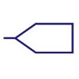 | Input Bus Line | Represents a bus for input or incoming data. |
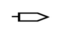 | Output Bus Line | Represents a bus for output or outgoing data. |
 | Terminal | Represents start or end point. |
 | Bus Line | A bus wire is made up of several conductors that are linked together. |
Switch Symbols
 | Pushbutton Switch (N.O) | When the button is pressed, this switch is in the ON position; otherwise, it is in the OFF position. |
 | Pushbutton Switch (N.C) | This switch is initially turned on. When this is released, it returns to the OFF state. |
 | DIP Switch | DIP switch is used for onboard configuration |
 | SPST Toggle Switch | SPST stands for Single Pole Single Throw. This serves as an ON/OFF switch. |
 | SPDT Toggle Switch | SPDT stands for single pole double throw. By altering its position, this switch permits current to flow in either of two directions. |
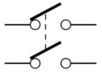 | DPST Switch | DPST stands for double pole single throw. This switch can power two circuits at the same time. |
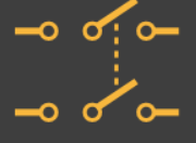 | DPDT Switch | DPDT is an abbreviation for double pole double throw. By adjusting the position, you may connect the four circuits. |
Ground Symbols
 | Earth Ground | Theoretically it is equivalent to 0V and is used as zero potential reference. |
 | Chassis Ground | It creates a barrier between the user and the circuit, preventing electric shock. |
 | Digital / Common Ground | It serves as a reference point against which the signal is measured. Because of voltage losses in a circuit, there may be many signal grounds. |
Relay Symbols
 | SPST Relay | SPST Stands for single-pole single-throw relay |
 | SPDT Relay | Single Pole Double Throw Relay (SPDT). The Relay consists of a coil, 1 common terminal, 1 normally closed terminal, and one normally open terminal. |
 | Jumper | Close connection by jumper insertion on pins. |
 | Solder Bridge | Solder to close connection |
Resistor Symbols
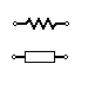 | Resistor (IEEE) | It is a device that is designed to opposes the flow of current in a circuit. These two symbols are used to represent fixed resistor. |
 | Potentiometer (IEEE) | Adjustable resistor – has 3 terminals. |
 | Potentiometer (IEC) | Adjustable resistor – has 3 terminals. |
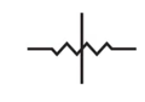
 | Variable Resistor / Rheostat (IEEE) | It is a variable resistor with two terminals. They are typically used to regulate the current in a circuit. Typically used in tuning circuits and power control applications such as heaters and ovens. |
 | Variable Resistor / Rheostat (IEC) | It is a variable resistor with two terminals. They are typically used to regulate the current in a circuit. Typically used in tuning circuits and power control applications such as heaters and ovens. |
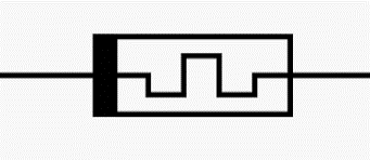
 | Trimmer Resistor | Preset resistor |
 | Thermistor | Thermal resistor – change resistance when temperature changes |
 | Photoresistor / Light dependent resistor (LDR) | Photo Resistors are another name for them. LDR resistance varies with the intensity of the incident light. They are commonly seen in light detecting applications. |
 | Attenuator | It is a device that reduces the power of a signal. They are constructed from basic voltage dividers and so belong to the resistor family. |
 | Memristor | The resistance of a memristor varies with the direction of charge flow. Memristors can be utilised in signal processing, logic/computation, non-volatile memory, and other applications. |
Capacitor Symbols
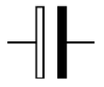
 | Non-Polarized Capacitor | Capacitor is used to store electric charge. It acts as short circuit with AC and open circuit with DC. |
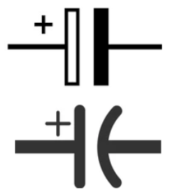 | Polarized Capacitor | Polarized capacitors have a small size but a large capacitance. They are utilised in direct current circuits. They can be used to bypass or pass low frequency signals as filters. |
 | Electrolytic capacitor | Almost all electrolytic capacitors are polarised and so used in direct current (DC) circuits. |
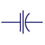
 | Variable Capacitor | The variable capacitor’s capacitance can be modified by turning the knob. They are commonly used to modify the frequency, or to tune. |
 | Feed through Capacitor | For high frequency transmissions, they provide a low impedance path to ground. |
Inductor / Coil Symbols
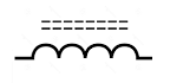
 | Iron Core Inductor | These are used to replace ferrite core inductors. Ferrite core inductors have a high permeability and require an air gap to lessen it. This air gap is built into iron powdered core inductors. |
 | Ferrite Core Inductors | The core material in these inductors is constructed of ferrite. These are generally used to reduce electromagnetic wave interference. |
 | Center Tapped Inductor | These are used in coupling of signals |
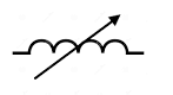 | Variable Inductor | The most popular type of variable inductors are movable ferrite magnetic core inductors. By moving the core in and out of the coil, the inductance may be changed. |
Power Supply Symbols
 | Voltage Source | It is a dependent voltage source. Usually depends on other sources (voltage or current). |
 | Current Source | Generates constant current. |
 | AC Voltage Source | This represents AC supply in the circuit. |
 | Generator | Electrical voltage is generated by mechanical rotation of the generator |
 | Battery Cell (DC) | This represents the DC power supply. It applies DC supply to the circuit. |
 | Battery | Combination of multiple single cell batteries or a single large cell battery. The voltage is usually higher. |
 | Controlled Voltage Source | Generates voltage as a function of voltage or current of other circuit element. |
 | Controlled Current Source | Generates current as a function of voltage or current of other circuit element. |
Meter Symbols
 | Voltmeter | Measures voltage. Has very high resistance. Connected in parallel. |
 | Ammeter | Measures electric current. Has near zero resistance. Connected serially. |
 | Ohmmeter | Measures resistance |
 | Wattmeter | Measures electric power |
Transformer Symbols
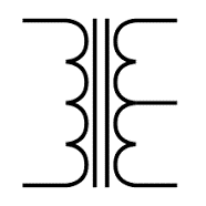
 | Transformer | The basic element that transmits energy from one circuit to the other by electromagnetic induction is the transformer. They are commonly used in electric power applications to increase or reduce the voltage of an alternating current. |
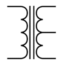
 | Iron Core Transformer | As a core, a piece of magnetic material is used. Iron and other ferro magnetic metals are commonly used. The magnetic field is contained by the core, which has a high permeability. |
 | Center Tapped Transformer | The secondary winding of a center-tapped transformer is divided into two portions, each with the same number of turns. This produces two distinct output voltages across two-line ends. Rectifier circuits use this. |
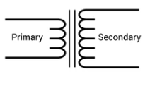 | Step Up Transformer | The number of turns in secondary winding more than that of primary winding. The output voltage exceeds the input voltage. Inverters make extensive use of it. |
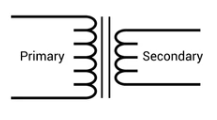 | Step Down Transformer | The number of turns in secondary winding is less than the number of turns in primary winding. The input voltage is greater than the output voltage. It’s common in low-power applications. |
Miscellaneous Symbols
 | Motor | Electric motor converts electrical energy to mechanical energy |
 | Electric bell | It is a sound producing device that rings when voltage is applied |
 | Buzzer | This is a sound-generating device. When the voltage is applied, a buzzing sound is produced. |
 | Fuse | The fuse disconnects when current above threshold. Used to protect circuit from high currents. |
 | Fuse | The fuse disconnects when current above threshold. Used to protect circuit from high currents. |
 | Bus | Contains several wires. Usually for data / address. |
 | Bus | Contains several wires. Usually for data / address. |
 | Bus | Contains several wires. Usually for data / address. |
 | Optocoupler / Opto-isolator | Optocoupler isolates connection to other board |
 | Loudspeaker | This is also an audio device. The electrical signal is converted into sound signal here. |
 | Microphone | Converts sound waves to electrical signal |
 | Operational Amplifier | Amplify input signal |
 | Schmitt Trigger | Operates with hysteresis to reduce noise. |
 | Analog-to-digital converter (ADC) | Converts analog signal to digital numbers |
 | Digital-to-Analog converter (DAC) | Converts digital numbers to analog signal |
 | Crystal Oscillator | Used to generate precise frequency clock signal |
 | Direct current | Direct current is generated from constant voltage level |
Table of Electronic Symbols
Transistor Symbol
 | NPN Bipolar Transistor | Allows current flow when high potential at base (middle) |
 | PNP Bipolar Transistor | Allows current flow when low potential at base (middle) |
 | Darlington Transistor | Made from 2 bipolar transistors. Has total gain of the product of each gain. |
 | JFET-N Transistor | N-channel field effect transistor |
 | JFET-P Transistor | P-channel field effect transistor |
 | NMOS Transistor | N-channel MOSFET transistor |
 | PMOS Transistor | P-channel MOSFET transistor |
Diode / LED Symbols
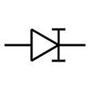
 | Diode | Diode allows current flow in one direction only – left (anode) to right (cathode). |
 | Zener Diode | Allows current flow in one direction, but also can flow in the reverse direction when above breakdown voltage |
 | Schottky Diode | It denotes a Schottky diode. It features a minimal forward voltage drop and switches quickly. Voltage clamping, rectifiers, reverse current, and discharge prevention are all applications for this material. |
 | Shockley Diode | This diode has four layers. Because of its quick switching function, it is useful in switching applications. |
 | Varactor / Varicap Diode | Varicap or variable capacitance diode is another name for a varactor diode. The capacitance of this diode varies with the applied voltage. This is utilised in frequency regulated oscillators, frequency multipliers, and other applications. |
 | Tunnel Diode | This is also known as Esaki diode. It can switch quickly and operate well in the microwave frequency band. This is employed in oscillator and microwave circuits. |
 | LED (Light Emitting Diode) | The light emitting diode is similar to the PN junction diode in that it emits energy in the form of light rather than heat. These are typically utilised in lighting and indicator applications. |
 | Photodiode | Photodiode allows current flow when exposed to light |
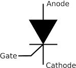 | Thyristor | It is made up of four layers of alternating P and N materials. They function as bistable switches and are employed in circuits with high voltages and currents. |
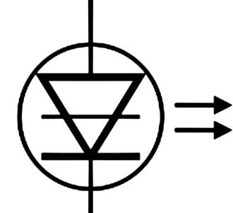 | Laser Diode | The laser diode is equivalent to the light emitting diode. In the PIN structure, the active region is produced in the intrinsic region. Laser diodes are used in laser printing, laser scanning, and other applications. |
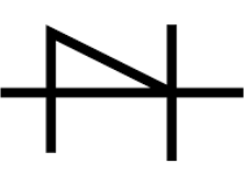
 | Constant Current Diode | Also known as a current limiting or current regulating diode. It restricts the current to a set maximum value. |
Antenna Symbols
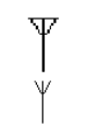 | Antenna / aerial | This symbol of Aerial or Antenna. It turns electrical power into radio waves. It’s utilised in wireless communication to send and receive signals. |
 | Loop Antenna | The loop antenna gets its name from the loop-like curvature of its wire or other electrical conductor. They are used as low-frequency reception antennas. |
 | Dipole Antenna | It is most commonly used antenna. Mainly used in set-top TV, shortwave transmission and FM receivers. |
Logic Gates Symbols
 | Inverter (NOT Gate) | Outputs 1 when input is 0 |
 | AND Gate | Outputs 1 when both inputs are 1. |
 | NAND Gate | Outputs 0 when both inputs are 1. (NOT + AND) |
 | OR Gate | Outputs 1 when any input is 1. |
 | NOR Gate | Outputs 0 when any input is 1. (NOT + OR) |
 | XOR Gate | Outputs 1 when inputs are different. (Exclusive OR) |
 | D Flip-Flop | Stores one bit of data |
 | Multiplexer / Mux 2 to 1 | Connects the output to selected input line. |
 | Multiplexer / Mux 4 to 1 | Connects the output to selected input line. |
 | Demultiplexer / Demux 1 to 4 | Connects selected output to the input line. |