
What is DC Motor?
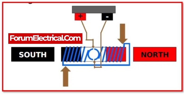
A Direct Current (DC Motor) motor is supplied by direct current. The operation of an electric motor is determined by the fundamental principles of electromagnetic. When a current-carrying conductor is placed within an external magnetic field, the resulting magnetic field will cause the conductor to experience a force that is proportional to the amount of current flowing through the conductor as well as the intensity of the magnetic field from the outside. It is a piece of equipment that can change the form that electrical energy takes into mechanical energy. The principle behind it is that a conductor that is carrying an electric current and is placed in a magnetic field would experience a force that will drive it to spin with respect to where it was initially positioned. A practical DC motor comprises of field windings, which are responsible for providing the magnetic flux, and an armature, which is the component that serves the function of the conductor.
Types of DC Motor:
The different types of DC motors are as follows:
- Series DC Motor,
- Shunt DC Motor,
- Compound Motor,
- Separately Excited DC Motor,
- Permanent Magnet DC Motor and
- Brushless DC Motor.
1). Series DC Motor:
A series motor is a type of DC series motor in which the field winding and the armature winding are connected internally in series to one another. The series motor has a high starting torque but must never be operated without a load. When it is first energised, it is able to move very heavy shaft loads. However, it must never be run without a load. There is another name for series motors, which is a series-wound motor.
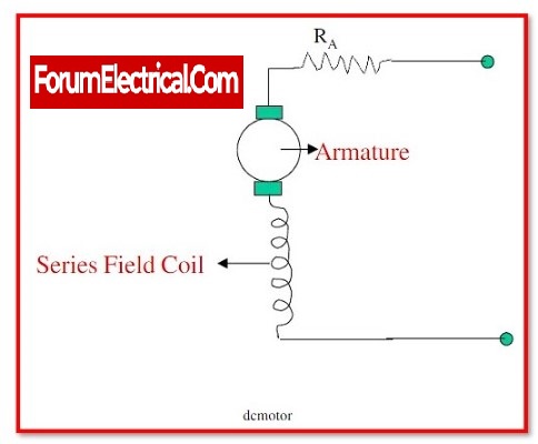
In motors with a series connection, the field windings are connected to the armature in a sequential manner. The magnitude of the field changes in response to changes in the armature current. When a load is applied to the series motor, it experiences a reduction in speed, which results in an increase in torque. It is superior to other types of DC motors in terms of its starting torque.
It is also able to radiate heat more easily, which is important because a huge quantity of current is being transmitted, which causes the winding to get hotter. When under full load, its speed is significantly different than when it is not under pressure. When the load is taken away from the motor, the speed of the motor increases, and the current flowing through the armature and field coils drops. The operation of huge machinery while they are unloaded causes damage.
When there is less current flowing through the field and armature coils, the strength of the flux lines that surround them will decrease. If the intensity of the flux lines that surround the coils were to be reduced at the same rate as the current that is flowing through them, then both variables would decrease at the same rate. It results in an increase in the motor’s speed.
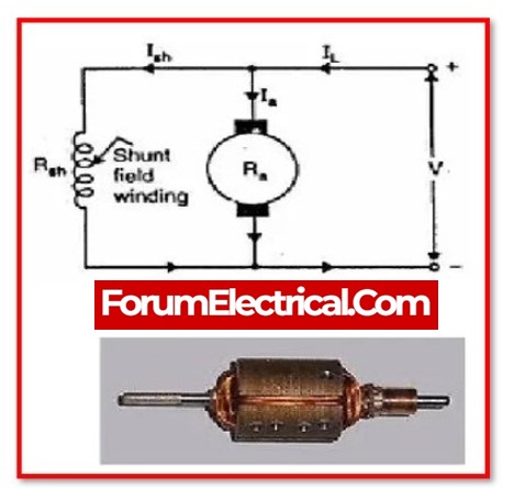
2). Shunt DC Motor:
In Shunt DC motors the field windings are shunted to or connected in parallel to the motor’s armature winding. Because of its effective speed regulation, shunt DC motors are widely employed. As a result, both the armature and field windings are exposed to the same supply voltage; nevertheless, there are discrete branches for the armature and field current flows.
A shunt motor has different operating characteristics than a series motor. Because the shunt field coil is made of tiny wire, it cannot produce a high starting current like the series field. This indicates that the shunt motor has a very low starting torque, which requires a low shaft load.
A very little amount of current passes through the shunt coil when voltage is applied to the shunt motor. The armature of a shunt motor is similar to that of a series motor, and it draws current to generate a high magnetic field. The motor starts to revolve because of the interaction of the magnetic field around the armature and the field generated around the shunt field.
When the armature starts to turn, it produces back EMF, just like a series motor. The back EMF will cause the current in the armature to drop to a very low level. When the motor achieves full speed, the amount of current drawn by the armature is proportional to the magnitude of the load. The armature current will be small because the load is normally small.
3). Compound Motor:
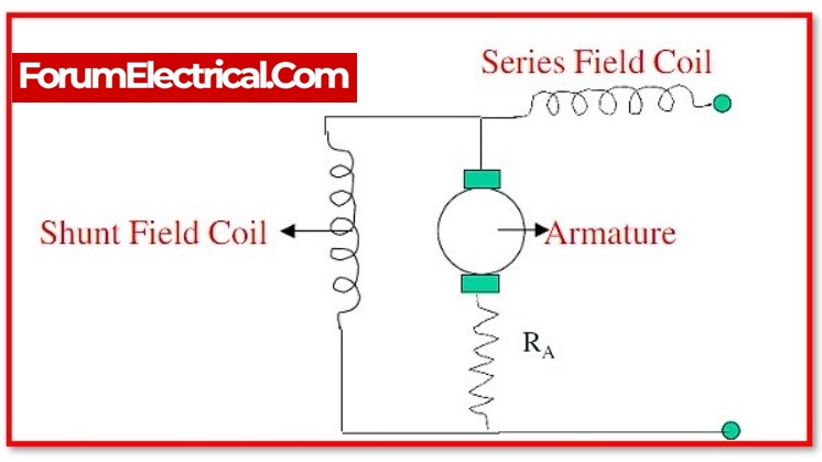
DC compound motors have a separately excited shunt field, which provides an appropriate starting torque but causes problems in variable speed applications. Despite these limitations, these motors are still widely used. These motors have the capability of having the field connected in series through the armature, in addition to having a shunt field that is excited separately.
While the shunt field provides enhanced speed regulation, the series field is responsible for generating a superior starting torque. However, the series field is not typically utilised in 4-quadrant drives since it creates control issues within the applications of variable speed drives and because it is not frequently used.
Compound Motor are classified into different types:
- Long Shunt Compound DC Motor,
- Short Shunt Compound DC Motor,
- Cumulative Compound DC Motor and
- Differential Compound DC Motor
4). Separately Excited DC Motor:
A separate DC source is used to energise the field windings and any additional coils in the device. Because the field winding is strengthened from a separate exterior DC current source, these motors have the specific characteristic that the armature current does not supply throughout the field windings. This is due to the fact that the field winding is strengthened by a separate DC current source.
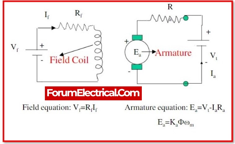
The equation for the torque produced by a DC motor is
Tg = Ka φ Ia
In this particular instance, the torque is changed by changing the value of the field flux “φ” and is independent to the armature current ‘’Ia’’.
5). Permanent Magnet DC Motor:
There is an armature winding in a permanent magnet DC motor. A permanent magnet is used to generate a field flux in these motors, and it is located on the inner edge of the stator core. The rotor, on the other side, includes a standard DC armature with brushes and commutator segments.
Permanent magnets are used to generate the magnetic field in direct current (DC) motors. Excitation, like that used in air conditioners, windscreen wipers, car starters, etc., does not use any of the input current.
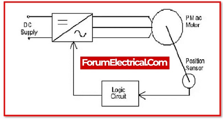
6). Brushless DC Motor:
A brushless DC motor’s input is current/voltage, and its output is torque. Identifying the working of a DC motor is very simple, as illustrated by the diagram below. A direct current motor is made up of two major components. The revolving component is called as rotor, while the stationary component is called as the stator. The rotor revolves around the stator.
The rotor is made of windings that are electrically connected to the commutator. The brushes, commutator contacts, and rotor windings are designed in such a way that when power is provided, the polarities of the energised winding and the stator magnets are misaligned, causing the rotor to move until it is approximately aligned with the stator’s field magnets.
The brushes move to the next commutator contacts and energise the next winding as the rotor approaches alignment. The revolution reverses the direction of current through the rotor winding, causing the magnetic field of the rotor to flip, causing it to continue rotating.
Which kinds of applications are most suitable for the use of DC motors?
DC motors are appropriate for a wide variety of applications, such as conveyors and turntables, as well as other uses that call for variable speed and either constant or low-speed torque. In addition to this, they perform well even in dynamic braking and reversing applications, both of which are common in a variety of industrial devices.
The most optimal selection in terms of application of DC Motor:
1). Smallest size:
Brushless DC motors are often the most power compact type of motor, and as a result, they allow you to pack the maximum amount of power into the smallest space feasible.
Brushed DC motors, which have a power density that is typically roughly 10% lower than steppers (hugely less power dense).
2). Accuracy with positioning:
The use of stepper motors is highly recommended in this case. This is the purpose that they were meant to accomplish. A typical stepper motor with 200 steps and a 1/128 micro-step controller like the ZD10 can provide up to 25600 places in a 360-degree circle.
Brushless DC motor, which is characterised by a high degree of precision (especially if using a large pole count and potentially adding a gearbox). Brushed DC are not suitable for this purpose at all.
3).High Speed:
By a large factor, brushless DC will achieve the highest possible speed. Following them brushed DC, which also has the ability to move at very high speeds. Stepper motors are not at all suitable for use in high-speed applications, so it’s best to avoid using them.
4). Lowest price:
Brushed DC is often the least expensive option. However, as the technology becomes more generally available, the cost of stepper and brushless DC solutions is reducing.
5). Efficient operation:
It would always recommend a high-grade brushed DC motor for applications such as turntables where smoothness is critical. Stepper motors can run relatively quietly, though not as quietly as brushed DC motors. Brushless DC motors may be considered for higher speed applications, but not stepper motors.
6). The Longest Durability:
Stepper motors and brushless DC motors are both options. There are some notable exceptions, such as motors made of precious metals, but in the great majority of circumstances, a brushless DC motor will be five to ten times longer than a brushed DC motor.
7). Low-speed performance:
At low speeds (1-100rpm), brushed DC and stepper motors perform effectively, but most brushless DC motors, especially those with low pole counts, perform poorly. If a brushless DC motor is chosen, a gearbox can reduce speed. A gearbox is required at <1rpm speeds and can be added to any motor type.
8). Maximum torque:
Without gears, a stepper motor (at low speed) will typically give the highest torque / power supplied. However, if high torque is important for the application, always recommend adding a gearbox to considerably improve torque. Depending on the other parameters in the application, any motor type could be the best alternative.
DC Motor selection requirements:
Finding out what voltage is easily accessible for the application and what physical size the motor needs to be are important parameters for picking a DC motor. Once the first two factors have been identified, speed and torque can be evaluated.
1. Voltage availability is an important consideration in motor selection. Remote applications and portable equipment, for example, are powered by batteries, but many rack-mounted devices and tools are powered by a 24V power source. DC motors can be used at voltages as low as 1.5V and as high as 48V, depending on the required power.
2. Physical size is frequently one of the limiting factors in motor selection, as more and more applications, such as desktop 3D printers, portable medical equipment, and hand tools, have smaller footprints. It is frequently necessary to strike a balance between the motor to be used and the available area.
3. As previously stated, torque and speed have an impact on motor frame size. High torque motors are frequently larger in size than low torque counterparts, implying that larger mounting hardware and housings may be required. For example, a greater motor is required to rotate the magnets in an MRI than it is to operate the windows in an automobile’s doors.
Although speed and torque are separate requirements in many applications, when the torque increases, the speed decreases if the voltage remains constant. The slope of the speed/torque curve is used to make this relationship.
4. Motor duty cycle is one of the most striking characteristics of many semi-conductor manufacturing machines. Intermittent operation not only reduces motor wear and tear and increases motor life, but it also allows for a smaller motor size to be used without decreasing the machine’s favourable qualities.