
Current Transformers (CTs) and Voltage Transformers (VTs) are important in ensuring accurate measurement, reliable protection and safe operation of electrical power systems.
During the commissioning phase of substations and industrial installations, thorough testing of CTs and VTs is essential to verify their performance, detect installation errors and ensure compliance with standards.
- Current Transformers (CT) and
- Voltage Transformers (VT/PT)
are essential components in electrical power systems.
They are used for measurement, protection and control purposes by stepping down high current and voltage levels into safe and measurable values.
What is Current Transformer (CT)?
A Current Transformer converts high primary current (e.g., 1000 A) into a low secondary current (1 A or 5 A). It is widely used in:
- Protection relays and
- Metering systems.
CT operates on the principle of electromagnetic induction.
When current flows through the primary conductor it induces a proportional current in the secondary winding.
Current transformers (CTs) are important power systems that measure and protect against overcurrent. Their accuracy class determines the accuracy with which they convert primary current to secondary current. IEC 61869-2 specifies standards for their performance & testing procedures.
What is Voltage Transformer (VT/PT)?
A Voltage Transformer converts high voltage (e.g., 11 kV) into low voltage (e.g., 110 V). It is used in:
- Voltage measurement
- Protection and control circuits
Similar to a power transformer, it works on mutual induction converting high voltage to a proportional low voltage.
CT Testing During Commissioning
CT testing ensures proper performance, safety and accuracy.
Primary Tests:
a). Polarity Test
Polarity Test ensures correct current direction (P1→P2 and S1→S2). Incorrect polarity can lead to relay malfunction.
b). Ratio Test
Ratio Test verifies CT ratio (e.g., 1000/5). It ensures correct scaling between primary and secondary.
c). Insulation Resistance Test
Insulation Resistance Test performed using a megger to check insulation:
- Primary to Secondary
- Secondary to Earth
d). Continuity Test
Continuity Test ensures secondary winding is not open. Open circuit in CT secondary can generate dangerous high voltage.
e). Burden Test
Burden Test checks whether connected load (relay/meter) is within CT rated burden.
f). Magnetization / Excitation Test
Magnetization / Excitation Test determines CT core characteristics and helps identify knee point voltage.
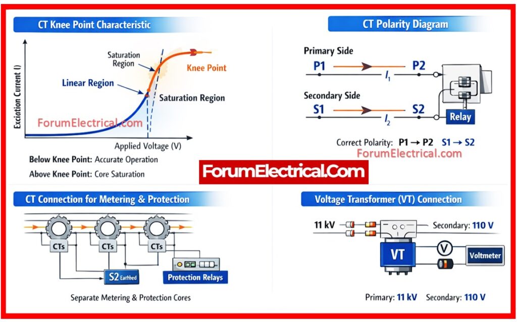
Knee Point of CT
The knee point is the voltage at which a small increase in voltage causes a large increase in current.
Standard Criteria
10% increase in voltage results in 50% increase in excitation current.
Practical Consideration
Below knee point: CT operates in linear region.
Above knee point: CT saturates → protection failure possible.
Knee Point Test Procedure
- Disconnect CT secondary from all equipment
- Connect test kit to CT secondary
- Apply increasing AC voltage gradually
- Record voltage and current readings
- Plot V-I curve
VT Testing During Commissioning
a). Polarity Test
Polarity Test ensures correct phase relationship
b). Ratio Test
Ratio Test verifies transformation ratio (e.g., 11kV/110V)
c). Insulation Resistance Test
Insulation Resistance Test checks insulation between windings and earth
d). Burden Test
Burden Test ensures load is within rated capacity
e). Secondary Voltage Check
Secondary Voltage Check verify output voltage with applied input
f). Phase Angle Error Test
Phase Angle Error Test is important for accurate metering systems.
Safety Notes
- Never open circuit CT secondary.
- Always short CT before disconnection.
- Ensure proper earthing.
- Knee point testing is critical for protection CTs.
- Accuracy is important for metering CTs.
Conclusion
Proper CT and VT testing during commissioning ensures system reliability, protection accuracy and operational safety.
Following these correct procedures helps prevent failures and ensures compliance with standards.
