 Test Procedure including insulation resistance, HV withstand, sheath integrity, tan delta, partial discharge and continuity tests for safe and reliable cable performance.)
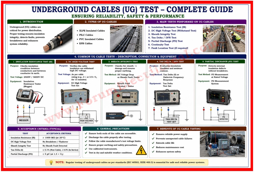
This document explains the standard test procedure for underground (UG) power cables prior to energization.
- Objective
- Scope
- References & Standards
- Safety Precautions
- Qualified Personnel
- Personal Protective Equipment (PPE)
- Safety Precautions
- Test Equipment Required
- Test Procedures
- Visual Inspection
- Continuity Test
- Insulation Resistance (IR) Test
- High Voltage DC / VLF Withstand Test
- Sheath Integrity Test
- Acceptance Criteria
- Documentation
Objective
The objective is to verify the electrical integrity of
- Cable insulation,
- Screen continuity and
- Sheath condition
following installation thereby ensuring safe and reliable operation of the cable system.
Scope
This procedure applies to all types of underground power cables installed for
- Low Voltage (LV),
- Medium Voltage (MV) and
- High Voltage (HV)
distribution and transmission systems which includes:
- Single core and multi core XLPE (or) EPR insulated cables,
- Armoured & unarmoured cable systems,
- Direct buried, ducted and trough installed cables and
- Cable joints, terminations & sealing ends.
References & Standards
| Standard / Code | Description |
| IEC 60502 | Power cables with an extruded insulation & their accessories. |
| IEC 60229 | Tests on cable oversheath / outer sheath. |
| IEEE 400 | Guide for the field testing of shielded power cable systems. |
| IS 7098 | Cross linked polyethylene insulated thermoplastic sheathed cables. |
| OSHA 1910.333 | Electrical safety — Selection and use of work practices. |
Safety Precautions
Qualified Personnel
All testing shall be performed by a qualified electrical engineer (or) a licensed cable testing technician.
A minimum of 2 persons should be present at all times during high voltage (HV) testing.
Personal Protective Equipment (PPE)
- Insulating rubber gloves rated for the test voltage,
- Safety goggles / face shield,
- Arc flash rated clothing (minimum Category 2),
- Insulating rubber mat at the test station and
- Safety boots with electrical hazard rating.
Safety Precautions
- Isolate all cable ends from the live conductors and confirm the absence of voltage using an approved voltage detector.
- Post warning signs as ‘High Voltage (HV) Testing in Progress’ at all cable ends & access points.
- Ensure the cable is discharged and earthed before connecting (or) removing any test equipment.
- Maintain radio communication between the team at the test set & the team at the far end.
- Obtain & display a valid Permit to Work (PTW) before the process of commencing.
Test Equipment Required
| Equipment | Specification / Range | Calibration Required |
| Insulation Resistance (IR) Tester | 500 V / 1 kV / 5 kV / 10 kV DC | Yes / Annual |
| High Voltage DC Test Set | 0-80 kV DC, 20 mA | Yes / Annual |
| Very Low Frequency (VLF) Test Set | 0.1 Hz, 0-52 kV AC | Yes / Annual |
| Continuity Tester / Low-Ohm Meter | Resolution: 0.01 mOhm (mΩ) | Yes / Annual |
| Sheath Fault Locator | Pulse reflection / TDR type | Recommended |
| Calibrated Measuring Tape | As required | No |
| Earth Resistance Tester | 0-2000 Ohm (Ω) | Yes / Annual |
Test Procedures
Visual Inspection
Before any electrical test is performed a thorough visual inspection shall be conducted:
- Confirm the cable route markers, joint bays and termination chambers are accessible & correctly identified.
- Inspect cable terminations and joints for any physical damage, moisture ingress, oil leaks (or) incorrect assembly.
- Check armour wire bonding & earthing connections at both ends.
- Record any defects with photographs & report immediately for the rectification before testing.
Continuity Test
To verify that conductor connections are complete with no open circuits.
- Short circuit and earth all the conductors at the far end of the cable.
- Using a continuity tester / low ohm meter measure the conductor resistance for each phase (L1, L2, L3) & neutral at the near end.
- Compare the measured resistance against the calculated value: R = rho x L / A (where rho – resistivity of conductor material, L – cable length, A – cross sectional area).
- Measured the values must not exceed the manufacturers specified resistance by more than 5%.
- Record all the results in the test datasheet.
Insulation Resistance (IR) Test
To assess the condition of cable insulation before applying a high voltage.
| System Voltage | Test Voltage (DC) | Min. Acceptable IR |
| Up to 1 kV | 1000 V DC | 100 MΩ |
| 1 kV – 11 kV | 5000 V DC | 1000 MΩ |
| 11 kV – 33 kV | 10000 V DC | 10000 MΩ |
- Ensure all the conductors are isolated and deenergised.
- Connect the IR tester across each conductor and earth by testing each combination: L1-E, L2-E, L3-E & L1-L2, L2-L3, L3-L1.
- Apply the test voltage for a time duration of 1minute (60 seconds) & record the reading.
- Polarisation Index to be calculated (PI = IR at 10 min/IR at 1 min). PI must be greater than 2.0 (> 2.0) for the acceptable insulation.
- Discharge the cable for at least 4 times the test duration before proceeding.
High Voltage DC / VLF Withstand Test
To confirm the dielectric integrity of the cable insulation under a stress conditions.
Method A: DC Withstand (for cables up to 33 kV)
- Apply DC voltage at a ramp rate not exceeding 1 kV/s up to the specified test voltage (typically 3 x U0 for 15 minutes).
- Monitor leakage current throughout. A stable or decreasing current is acceptable. A rising (or) fluctuating current indicates a fault.
- If the cable withstands the testing voltage for the full complete duration without breakdown, it passes.
Method B: VLF Withstand (preferred for XLPE/EPR cables)
- Connect the VLF test set at 0.1 Hz. Apply 3 x U0 AC voltage for 1 hr (60 minutes).
- Monitor for partial discharge activity and if PD measurement is integrated in the test set.
- Failure (flashover/breakdown) at any point constitutes a test rejection.
Sheath Integrity Test
- To verify that the outer sheath & bedding are intact & provide adequate protection for the metallic screens and armour.
- Disconnect all the screen and armour earth connections at both ends.
- Apply 5 kV DC between the metallic screen/armour & earth for 1 minute (60 seconds).
- Minimum acceptable insulation resistance of the outer sheath: 1 MΩ per km of cable length.
- If a sheath fault is indicated utilize a TDR (or) sheath fault locator to pinpoint the fault location for repair.
Acceptance Criteria
| Test | Parameter | Acceptance Criteria |
| Continuity | Conductor Resistance | Within 5% of calculated value |
| IR Test | Insulation Resistance | Per voltage class (see 6.3) |
| IR Test | Polarisation Index | PI > 2.0 |
| HV / VLF Withstand | Withstand (no breakdown) | No flashover / leakage stable |
| Sheath Integrity | Sheath IR | Min. 1 MΩ/km |
Documentation
All test results shall be recorded on the UG Cable Test Report Form.
The report shall include:
- Cable identification, rating, length and installation date.
- Test equipment details, serial numbers and calibration certificates.
- Ambient temperature & humidity at time of testing.
- Individual test readings for every phase & each test type.
- Pass (or) Fail status for each test.
Completed test reports shall be submitted to the Project Engineer within 24 hours of testing & archived in the project quality file for the duration of the cables service life.