Black Start Procedure
Black Start Procedure is one of the most important emergency operations in modern power engineering.
It refers to the controlled process of restoring the electrical power to a network following a complete system blackout that is a condition where no external grid supply is available to support the restart.
- Black Start Procedure
- Why Black Start Capability Important?
- Equipment Used in Black Start Operations
- Black Start Generator / Emergency DG Set
- DC Battery Bank & Battery Charger System
- Auxiliary Transformer
- Protection & Control Relays
- Synchronization System
- SCADA & Communication Systems
- Black Start Restoration Procedure
- Voltage & Frequency Control during Restoration
- Critical Precautions & Safety Requirements
- Practical Engineering Insights
The term “black start” derives from the concept of bringing a completely dead (black) power system back to working condition without any outside assistance.
In a total grid collapse condition, every
- Substation,
- Transformer and
- Generator is de-energized.
No voltage, no frequency and no synchronization reference exists.
Under these conditions conventional generators cannot self-start because they depend primarily on station auxiliary power to energize
- Field excitation systems,
- Cooling fans,
- Lubrication pumps and
- Control circuits.
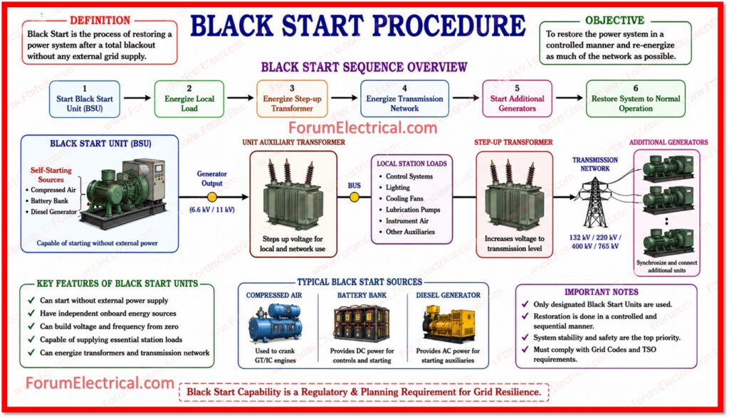
Only specially designated Black Start units are designed to self-start from a completely dead state utilizing onboard energy sources such as compressed air, battery banks (or) dedicated diesel generators.
Black Start capability is not only a technical necessity but also a regulatory & planning requirement in most national & regional grid codes worldwide.
Transmission system operators (TSOs) & grid regulators as a mandate that a defined number of generators within each zone maintain a certified Black Start capability to ensure system resilience.
Why Black Start Capability Important?
The consequences of a major grid blackout without an organized Black Start strategy can be catastrophic & long-lasting.
| Importance of Black Start Planning | |
| Grid Resilience | Ensures that the power system can recover independently from a complete collapse reducing dependency on the neighbouring grids. |
| Minimized Outage Duration | Coordinated restoration can reduce the blackout duration from days to hours and protect important infrastructure. |
| Economic Protection | Extended blackouts may cause massive economic losses. Industries, hospitals & transport grids depend on rapid restoration. |
| National Security | Power is essential to the defense systems, communications, water treatment and emergency services. Black Start protects all these assets. |
| Regulatory Compliance | Grid operators are legally needed to maintain Black Start capability under national & international grid codes. |
Equipment Used in Black Start Operations
A successful Black Start operation depends on major key equipment categories. Each component plays a specific and important function in the restoration sequence.
Black Start Generator / Emergency DG Set
Black Start Generator / Emergency DG Set is the primary energy source during blackout restoration.
These generators are designed to self-start without any external power supply.
They are typically diesel driven & sized to supply auxiliary loads for the main generating unit.
Key requirements include rapid startup time i.e.,: (typically within 10–30 seconds), automatic voltage regulation (AVR) and governor control for frequency stability.
DC Battery Bank & Battery Charger System
The DC system is the lifeline of the complete restoration process.
During a blackout the AC supply for control systems is lost.
The battery bank provides uninterrupted DC power for the protection relay operation, circuit breaker trip and close coils, SCADA and communication systems, and indication and alarm panels.
Battery banks are typically 110V DC (or) 220V DC systems with sufficient autonomy for 4 to 8 hours.
Auxiliary Transformer
The auxiliary transformer steps down the generator terminal voltage (typically 11 kV or 6.6 kV) to the station service voltage (415V or 3.3 kV) needed for auxiliary equipment such as pumps, fans and control panels.
Energizing the auxiliary transformer is one of the first major steps after the Black Start generator that achieves stable output.
Protection & Control Relays
Protection relays should remain healthy throughout the blackout period.
Modern numerical relays with internal battery backup (or) UPS support maintain their settings and self monitoring functions even during the outages.
These include
- Overcurrent relays,
- Distance protection,
- Differential protection and
- Busbar protection
all of which should be verified before energizing any circuit.
Synchronization System
Before connecting any generator to an energized busbar (or) grid section synchronization should be achieved.
The synchronization panel (or) automatic synchronizer verifies that the voltage magnitude, frequency and phase angle between the incoming machine & the busbar are within acceptable limits.
Incorrect synchronization can cause a severe mechanical shock to the generator & electrical disturbance to the system.
SCADA & Communication Systems
The Supervisory Control and Data Acquisition (SCADA) system provides a real-time monitoring & remote control capability during the restoration sequence.
Communication systems which includes
- Power Line Carrier (PLC),
- Fiber optic and
- Radio links
allow coordination between the control center, power plants and substations throughout the restoration process.
Black Start Restoration Procedure
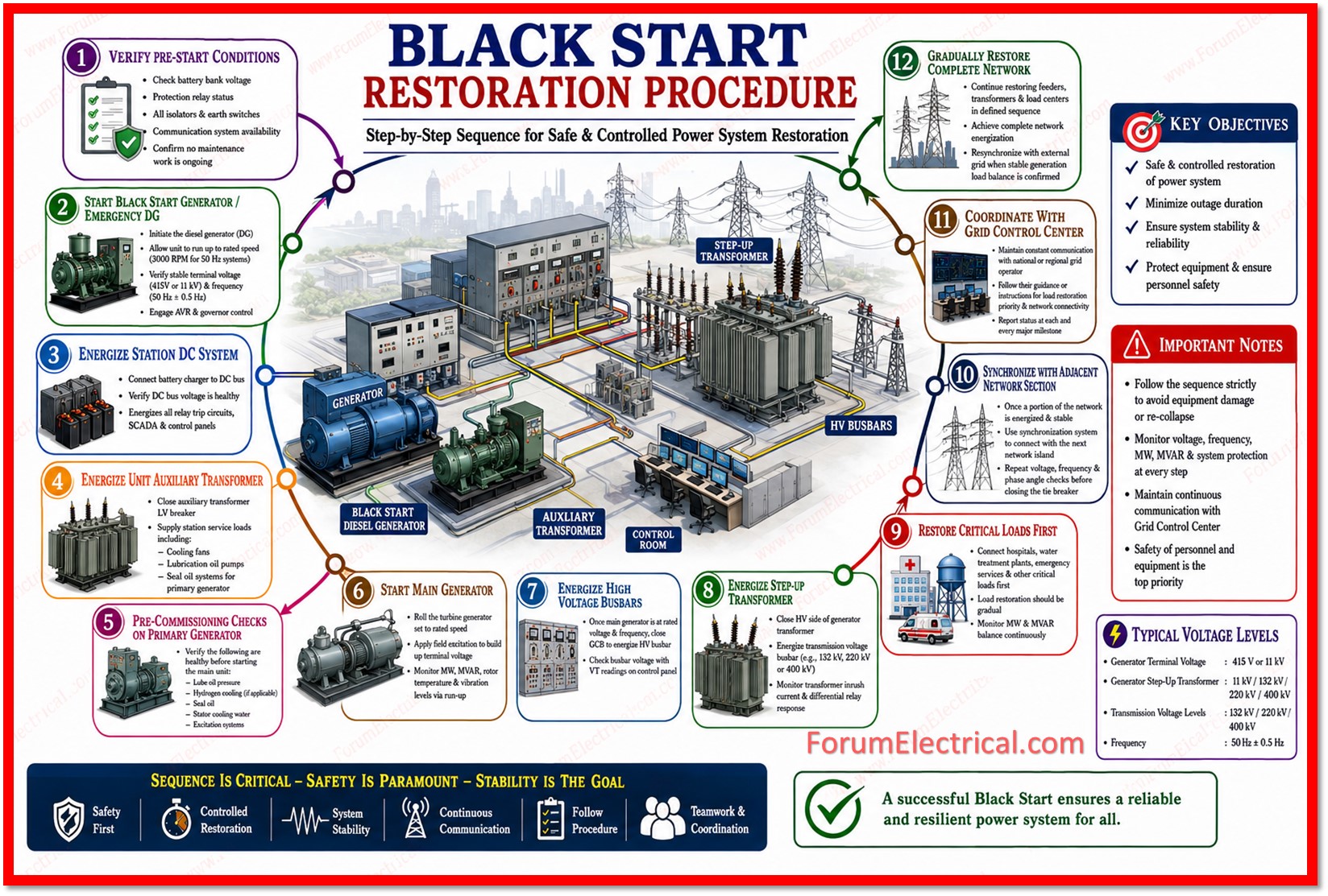
The Black Start restoration sequence is a defined, step-by-step procedure that should be followed methodically.
Deviating from the sequence may result in system damage (or) re-collapse.
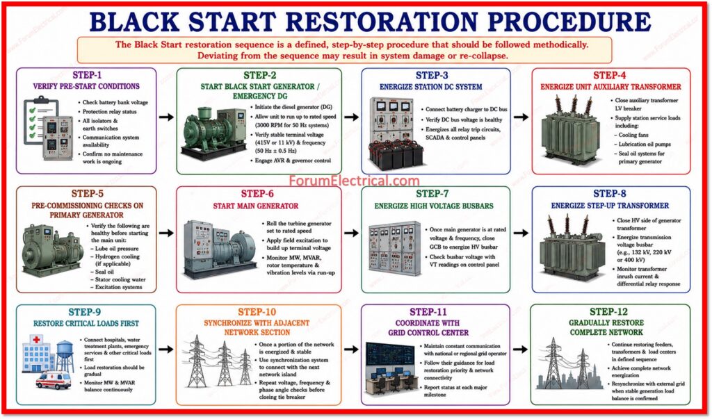
The following describes each steps in detail:
Step-1: Verify Pre-Start Conditions: Check battery bank voltage, protection relay status, all isolators & earth switches and communication system availability. Confirm no maintenance work is ongoing on the important equipment.
Step-2: Start Black Start Generator / Emergency DG: Initiate the diesel generator (DG). Allow the unit to run up to rated speed (3000 RPM for 50 Hz systems). Verify the stable terminal voltage (which is typically 415V or 11 kV) & frequency (50 Hz ± 0.5 Hz). Engage the AVR & governor control.
Step-3: Energize Station DC System: Connect the battery charger to the DC bus. Verify the DC bus voltage is healthy. This energizes all relay trip circuits, SCADA & control panels.
Step-4: Energize Unit Auxiliary Transformer: Close the auxiliary transformer LV breaker to the supply station (Substation Transformer) service loads including cooling fans, lubrication oil pumps & seal oil systems for the primary generator.
Step-5: Pre-Commissioning Checks on Primary Generator: Verify the lube oil pressure, hydrogen cooling (if applicable), seal oil, stator cooling water & excitation systems are all healthy before starting the main unit.
Step-6: Start Main Generator: Roll the turbine generator set to a rated speed. Apply field excitation to build up the terminal voltage. Monitor the active and reactive power output, rotor temperature and vibration levels via run-up.
Step-7: Energize High Voltage Busbars: Once the main generator is at rated voltage & frequency close the generator circuit breaker (GCB) to energize the HV busbar. Check the busbar voltage with a VT readings on the control panel.
Step-8: Energize Step-Up Transformer: Close the HV side of the generator transformer to energize the transmission voltage busbar (e.g., 132 kV, 220 kV (or) 400 kV). Monitor the transformer inrush current & differential relay response.
Step-9: Restore Critical Loads First: Connect hospitals, water treatment plants, emergency services & other critical loads first. Load restoration should be gradual as sudden load pickup may cause a frequency dip & voltage collapse. Monitor MW & MVAR balance continuously.
Step-10: Synchronize with Adjacent Network Section: Once a portion of the network is energized & stable then utilize the synchronization system to connect with the next network island. Repeat voltage, frequency & phase angle checks before closing the tie breaker.
Step-11: Coordinate with Grid Control Center: Maintain a constant communication with the national (or) regional grid operator. Follow their guidance or instructions for the load restoration priority & network connectivity. Report the status at each and every major milestone.
Step-12: Gradually Restore Complete Network: Continue the restoring feeders, transformers & load centers (LDC) in a defined sequence until complete network energization is achieved. Resynchronize with the external grid when a stable generation load balance is confirmed.
Voltage & Frequency Control during Restoration
Two parameters that demand a constant attention via the Black Start procedure is
- Voltage and
- Frequency.
These are the base of power system stability & their deviation beyond the acceptable limits at any stage and can undo the entire restoration effort.
Voltage Control
- Maintain the generator terminal voltage within ±5% of nominal throughout restoration.
- Monitor the transformer tap changer positions and adjust as load is added.
- Use reactive power (MVAR) from the generators to support voltage during the feeder energization.
- Ferranti Effect: when energizing long transmission lines with no load the receiving end voltage can rise significantly and this should be controlled by limiting the line length (or) using reactive compensation.
Frequency Control
- Maintain system frequency at 50 Hz ± 0.2 Hz during a normal restoration.
- Load pickup should be gradual as sudden large load connections may cause frequency decay.
- Governor droop settings on the generators control load sharing during island operation.
- Under-frequency load shedding (UFLS) relays should be verified healthy throughout the procedure.
Critical Precautions & Safety Requirements
The following precautions are non-negotiable during any Black Start operation.
- Always verify the protection relay status and their settings before energizing any equipment.
- Confirm all the earth switches are open and isolation is correct before energizing any circuit.
- Never bypass the protection relays during restoration to speed up the procedure.
- Monitor the DC bus voltage continuously and loss of DC during the restoration may cause protection failure.
- Use the interlock systems and key interlocks to prevent switching errors.
- Confirm the communication links are live with all key important substations before proceeding.
- Maintain a written log (record) of every switching operation with timestamps.
- Have trained operator teams on standby at each substation & power plant.
- Verify the generator reactive capability charts to prevent the loss of synchronism during island operation.
- All the personnel should follow the Safety Rules, Permit to Work and LOTO (Lockout/Tagout) procedures.
Practical Engineering Insights
In practice, Black Start procedures are regularly conducted by power utilities as part of their emergency preparedness programs.
These were used to test the readiness of equipment, operators and procedures under simulated blackout conditions.
Several engineering realities make Black Start operations challenging:
- Not all generators can Black Start. Only units with self starting capability (typically hydro plants, gas turbines, or diesel units) are certified.
- Large steam turbines require hours of warm-up time & cannot participate in immediate Black Start and they are loaded later in the restoration sequence.
- Transformer inrush current during energization may operate differential protection and restoration engineers should account for this with inrush restraint settings.
- In some conditions Black Start service providers are compensated via capacity payments for maintaining this capability.
- Modern power systems with high renewable penetration face the new Black Start challenges as solar and wind farms cannot inherently provide Black Start capability without any grid-forming inverters.

