
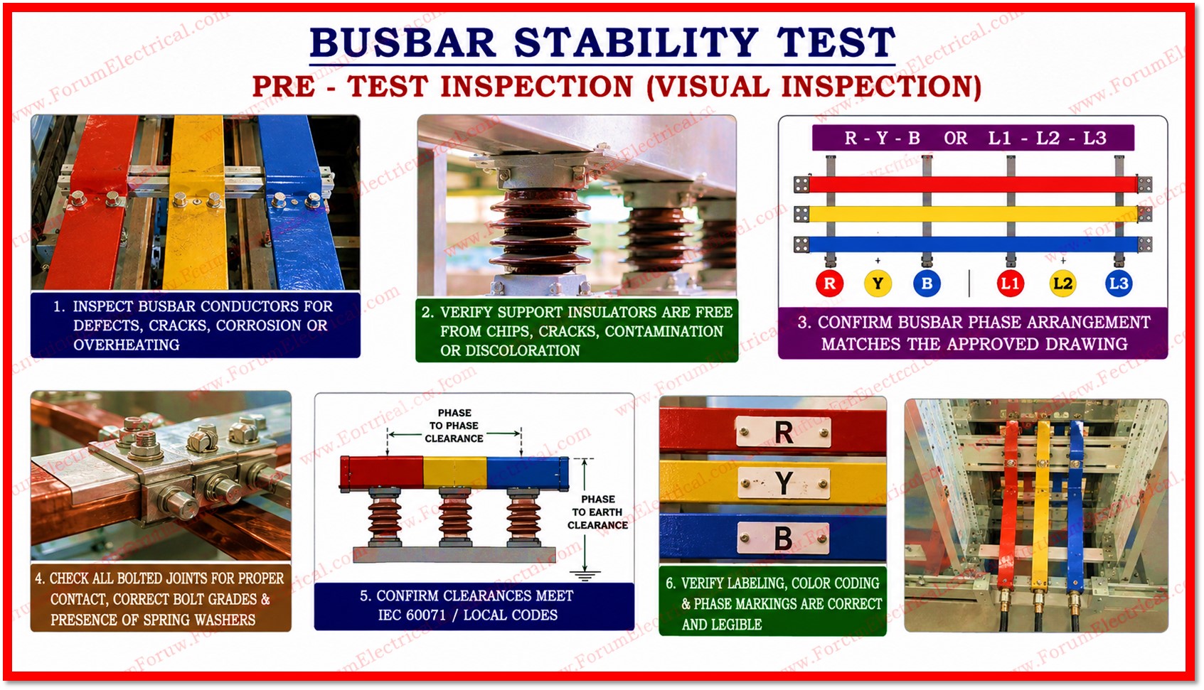
A busbar differential protection mechanism is tested for stability under normal operating settings & external fault conditions using the busbar stability test.
The test maintains the differential relay steady & proper when balanced busbar currents flow.
- Purpose
- Objective
- Scope
- Safety Precautions
- Standards
- Required Equipment
- Pre Test Inspection
- Visual Inspection
- Dimensional Verification
- Test Procedure
- Contact Resistance Test
- Insulation Resistance Test
- Power Frequency Withstand (Hi-Pot) Test
- Thermal Stability Test
- Short-Circuit Withstand / Mechanical Stability Test
- Acceptance Criteria
- Test Documentation
Before commissioning or maintenance, engineers can test relay performance, CT polarity, wire integrity & protection dependability by injecting equal currents into all busbar zone CT circuits.
This test prevents undesired trips and ensures substation busbar protection system safety.
Purpose
This procedure is used to define the standardized methodology for conducting stability tests on busbars that is used in medium and high voltage switchgear assemblies, distribution panels and power substations.
Objective
The objective is to verify the mechanical, thermal and electrical integrity of busbar systems under rated & fault conditions ensuring safe and reliable operation throughout their service life.
Stability testing ensures that busbar installations that comply with applicable national and international standards & that they are capable of withstanding electrodynamic forces generated during short circuit without structural failure (or) dangerous deformation.
Scope
This procedure applies to:
- Copper and aluminium busbars utilized in LV, MV & HV switchgear panels.
- Busbar trunking systems (busducts) in industrial & commercial installations.
- Substation busbars rated up to 33 kV.
- Retrofit (or) newly commissioned busbar assemblies requiring acceptance testing.
Safety Precautions
The following safety measures should be strictly observed prior to and during all testing activities:
- Obtain a valid Permit to Work (PTW) prior to commencing any test activity.
- Isolate, earth & lock out/tag out (LOTO) all power sources connected to the busbar system.
- Wear appropriate Personal Protective Equipment (PPE) which includes insulated gloves, arc flash suit, face shield & safety boots rated for the voltage level.
- Keep a minimum safe distance as per the applicable arc flash boundary calculations.
- Ensure a fire extinguisher (CO2 type) & first aid kit are readily available at the test site.
- Do not perform tests during adverse weather conditions for the outdoor switchyards.
Standards
- IEC 60865-1
- IEC 61439
- IEEE Std 605
- NFPA 70E
- IEC 60071
Required Equipment
| Equipment | Specification | Purpose |
|---|---|---|
| Digital Low Resistance Ohmmeter | Resolution: 0.1 µΩ, Range: 0–200 mΩ | Contact resistance measurement |
| High Current Test Set | Up to 10,000 A, AC/DC | Short circuit force simulation |
| Thermographic Camera (IR) | Range: -20°C to 650°C, ±2% accuracy | Thermal stability verification |
| Insulation Resistance Tester | 500V / 1000V / 5000V DC | Insulation integrity check |
| Digital Torque Wrench | 5-150 Nm with ±3% accuracy | Fastener torque verification |
| Vernier Caliper / Micrometer | 0.01 mm resolution | Dimensional inspection |
| High Voltage (HV) AC Test Set | Up to 50 kV & 50/60 Hz | Power frequency withstand test |
| Personal Protective Equipment | Arc-rated and per NFPA 70E / IEC 61482 | Personnel safety |
Pre Test Inspection
Visual Inspection
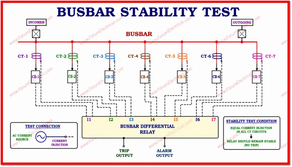
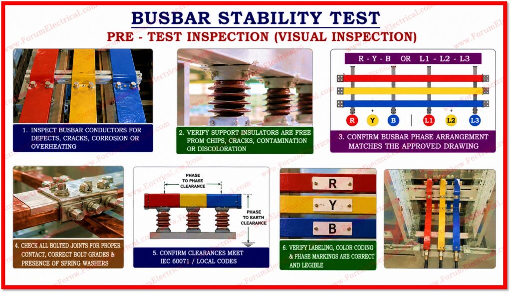
Before initiating any electrical tests perform a thorough visual inspection of the busbar assembly.
Inspect all busbar conductors for the surface defects, cracks, corrosion (or) signs of overheating.
Verify that all support insulators are free from chips, cracks, contamination (or) discoloration.
Confirm that the busbar phase arrangement (R-Y-B or L1-L2-L3) matches the approved drawing.
Check all the bolted joints for proper contact, correct bolt grades & presence of spring washers.
Confirm phase-to-phase & phase-to-earth clearances meet IEC 60071 / local codes.
Verify that all the labeling, color coding & phase markings are correct and legible.
Dimensional Verification
Measure & record the following dimensions against the approved design drawings.
Cross sectional dimensions of each busbar conductor (width x thickness).
Phase-to-phase spacing and phase-to-earth clearance.
Support insulator spacing & clamp arrangement.
Expansion gap provisions for the thermal elongation.
Test Procedure
Contact Resistance Test
Purpose
To verify that all the bolted joints have acceptable contact resistance values that is ensuring minimal heat generation under load.
Calibrate the Digital Low Resistance Ohmmeter & set to appropriate range (µΩ).
Apply test current of minimum 100 A DC across each bolted joint.
Measure resistance at each joint & record the value.
Acceptance Criteria
Contact resistance should not exceed 10 µΩ per joint (or) the manufacturer’s specified value & whichever is lower.
Any joint exceeding the limit should be re-torqued & re-tested.
Insulation Resistance Test
Purpose
To confirm the insulation integrity of the busbar system before energization.
Use an insulation resistance tester at 1000V DC for LV & 5000V DC for MV systems.
Measure IR between each phase conductor & earth & between phases.
Duration
Apply test voltage for 60 seconds and record reading.
Acceptance Criteria
IR value should be greater than 100 MΩ at 20°C
Power Frequency Withstand (Hi-Pot) Test
Purpose
To verify that the busbar insulation can withstand the required dielectric stress.
Connect the HV AC test set to the busbar under test with all other phases earthed.
Gradually increase test voltage from 0 to the specified value (per IEC 60865 Table 1) over 10 seconds.
Maintain test voltage for 60 seconds.
Reduce voltage gradually & record observations as no flashover (or) breakdown is permitted
Thermal Stability Test
Purpose
To confirm the busbar temperature rise does not exceed permissible limits under continuous rated current.
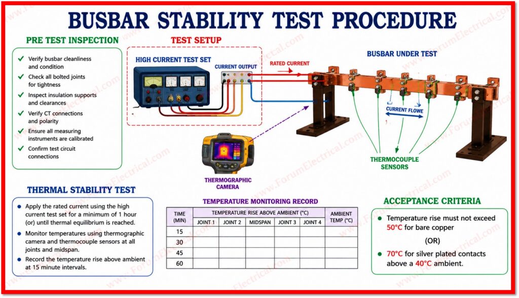
Apply the rated current using the high current test set for a minimum of 1 hour (or) until thermal equilibrium is reached.
Monitor temperatures using thermographic camera and thermocouple sensors at all joints and midspan.
Record the temperature rise above ambient at 15 minute intervals.
Acceptance Criteria
Temperature rise must not exceed 50°C for bare copper (or) 70°C for silver plated contacts above a 40°C ambient.
Short-Circuit Withstand / Mechanical Stability Test
Purpose
To verify the busbar assembly can withstand the electrodynamic forces during a short circuit fault without permanent deformation (or) structural failure.
Set the high current test set to deliver the rated short circuit current (Ipk) for the specified duration (typically 1 second)
Monitor busbar deflection using dial gauges (or) optical sensors at midspan.
After the test conduct a thorough visual inspection of all supports, insulators and fasteners.
Measure busbar deflection and permanent set should not exceed 1% of the support span
Re-check the contact resistance at all joints post short circuit test.
Acceptance Criteria
| Test | Parameter | Acceptance Limit |
|---|---|---|
| Contact Resistance | Per bolted joint | ≤ 10 µΩ |
| Insulation Resistance | Phase to Earth / Phase to Phase | ≥ 100 MΩ at 1000V DC |
| Hi-Pot Test | No flashover (or) breakdown | Per IEC 60865 Table 1 |
| Thermal Stability | Temperature rise above ambient | ≤ 50°C (bare) / ≤ 70°C (plated) |
| Short-Circuit Withstand | Permanent deflection | ≤ 1% of support span |
Test Documentation
All test results will be recorded in the busbar stability test report form (EE-BST-FR-001).
The following shall be documented:
- Test date, location and ambient temperature/humidity.
- Equipment identification: busbar rating, material, manufacturer & drawing reference.
- Instrument calibration certificates & serial numbers.
- Measured the values for each test with pass/fail status.
- Photographs of any defects, post-test condition & thermal images.