
Current Transformers (CTs) are the primary fundamental measuring instruments in power system protection schemes.
- CT Polarity
- CT Polarity during Internal Faults
- What is an Internal Fault?
- Current & Polarity Response
- CT Polarity during External Faults
- What is an External Fault?
- Current & Polarity Response
- Comparison
- Practical Considerations & Common Issues
- CT Polarity Reversal
- CT Saturation during External Faults
- Verification during Commissioning
- References & Standards
- Conclusion
They step down high primary currents to standard secondary values which is typically 1 A or 5 A enabling relay and metering equipment to operate safely.
However the effectiveness of any protection scheme that uses multiple CTs particularly differential protection is essentially dependent on the correct polarity of the CTs involved.
The terminal-marking convention states that when current enters the primary polarity terminal P1, the secondary current exits the secondary polarity terminal S1. Multiple CTs in a protection circuit must have the correct polarities so the relay can distinguish internal and exterior faults.
Relay maloperation due to incorrect polarity can cause superfluous tripping under normal or external fault conditions (or) failure to trip during internal faults.
CT Polarity
CT polarity is typically indicated by a dot convention (or) by marking terminals as P1/P2 on the primary & S1/S2 on the secondary.
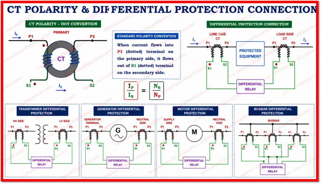
The standard convention states:
- When current flows into the P1 (dotted) terminal on the primary side it flows out of the S1 (dotted) terminal on the secondary side.
- The ratio & phase relationship are maintained strictly according to this convention.
- In protection schemes the CT connections are arranged so that under load and external fault conditions and the relay measuring element sees little (or) no differential current while an internal fault causes a large non zero differential quantity sufficient to operate the relay.
For differential protection, one of the most common methods for
requires connecting the CTs on both ends of the protected equipment so that the relay differential measuring element sees small (or) no net current under normal load or through-fault (external fault) conditions and a significant differential quantity under internal fault conditions.
CT Polarity during Internal Faults
What is an Internal Fault?
An internal fault is any fault that occurs within the protected zone that is the electrical equipment (or) busbar section bounded by the CTs of the differential protection scheme.
Examples
- Winding-to-earth faults in a transformer
- Inter-turn short circuits in a generator stator
- Phase-to-phase faults within a protected bus section.

Current & Polarity Response
During an internal fault current flows into the protected zone from the both ends (feeding sources).
When CTs are correctly polarised:
- The CT secondary currents appear in the same operating direction at the relay differential measuring element.
- The currents add together generating a significant non zero vector sum at the differential element.
- A significant differential current is generated because the CT secondary currents appear in the same operating direction creating a large non zero vector sum that exceeds the relay pickup threshold.
- The protection relay operates & sends a trip command to the associated circuit breakers.
This is the intended function of a differential protection scheme.
The CT polarity ensures that the vector sum of all currents measured at the boundary of the protected zone is non zero during an internal fault that is directly causing relay operation.
The magnitude of the differential current is proportional to the fault severity & the relay responds rapidly which is typically within 20-40 ms in modern numerical relays.
CT Polarity during External Faults
What is an External Fault?
An external fault also known as a through fault occurs outside the protected zone but still within the power system.
The fault current passes through the protected zone from one terminal to the other stressing the equipment thermally & mechanically but not requiring the differential relay to operate.
Current & Polarity Response
During an external fault the current ideally enters the protected zone at one terminal & exits at the other.
In practice however the 2 CT secondary currents are not perfectly equal due to
CT ratio error,
- Excitation current,
- CT saturation,
- Burden and lead resistance mismatch,
- Tap-changer position (in transformer schemes) and
Relay measurement tolerances:
- With correct CT polarity the secondary currents from the 2 CTs appear in opposing directions at the relay differential measuring element.
- The currents largely cancel at the differential element resulting in a small residual spill current rather than a true zero ideally near zero but practically a small residual exists due to CT and system errors.
- The relay correctly remains restrained & does not issue a trip command.
- Load current & through-fault current therefore do not cause unwanted relay operation.
Well-designed differential protection schemes exhibit restraint.

Differential relays use a percentage restraint (or) bias characteristic to stay stable because a small spill current always exists under external fault and load conditions.
The relay only operates as the differential current exceeds a defined proportion of the restraint (through) current.
Without correct CT polarity a substantial false differential current could occur under through fault conditions leading the relay to trip unnecessarily causing healthy equipment to lose supply & network cascade failures.
Comparison
The following table summarizes the key differences in CT polarity between internal and external fault conditions.
| Parameter | Internal Fault | External Fault |
| CT Polarity | Currents Add Up | Currents Cancel Out |
| Differential Current | High (operates relay) | Near Zero (no operation) |
| Relay Response | TRIP | RESTRAIN |
| Current Direction | Same direction in relay | Opposing direction in relay |
Practical Considerations & Common Issues
CT Polarity Reversal
A reversed CT polarity is one of the most common commissioning errors in protection systems.
In a simple two end differential scheme reversing one CT polarity causes the load (or) through current contributions to add instead of cancel at the relay differential element generating a large false differential current.
In the ideal equal current case this false differential current may approach twice the load current leading to spurious tripping.
During an external fault the same effect occurs: the currents add rather than cancel and the relay operates incorrectly.
Polarity reversal can be rectified by swapping the CT secondary terminals (or) in numerical relays by inverting the relevant current input in the relay settings that is provided the wiring is clearly documented.
CT Saturation during External Faults
With properly polarized CTs large external faults can saturate one (or) more CTs distorting the secondary current waveform & causing a false differential current.
Modern numerical differential relays use
- % constraint,
- Multi-slope bias,
- External-fault detection logic or
- CT saturation detection algorithms for stability.
Note:
Second harmonic constraint is mostly used in transformer differential protection to block magnetising inrush not CT saturation during external faults.
CT saturation risk can be reduced by carefully selecting the CT protection class, saturation performance, excitation characteristics, burden capability & knee point voltage to preserve relay stability at maximum through fault conditions.
The knee point voltage is the main sizing parameter for PX/PS/Class X CTs in high-impedance schemes while the accuracy class, rated equivalent limiting primary current (ALF) & transient performance (TPX/TPY/TPZ) are important for IEC 5P/10P & ANSI C-class CTs in low impedance numerical relays.
Verification during Commissioning
CT polarity should always be verified during commissioning using the following methods:
- Primary injection testing: Injecting current via the primary circuit and verifying secondary current direction with a milliammeter (or) clamp meter.
- Secondary injection testing: Applying current to the relay terminals & verifying correct directional response in the relay logic.
- Continuity and polarity checks: Using a battery & galvanometer to confirm the polarity markings match the physical connections.
- Modern relay event records: Reviewing pre commissioning test event data to confirm that load current generates zero (or) near zero differential current.
References & Standards
- IEC 60044-1
- IEC 61869-2
- IEEE C37.110
- IEC 60255
Conclusion
Power system protection depends on CT polarity.
Polarized CTs ensure the relay functions reliably for internal faults & stays stable during load flow & external faults in differential protection configurations.
Internal fault causes secondary currents to develop and trip the relay operational element.
Countercurrents from external faults preserve relay constraint & system stability.
For protection system reliability & security CT polarity should be considered throughout design, installation and commissioning.
Recent numerical relays allow current input polarity inversion (or) software adjustment for wire polarity difficulties during commissioning but this should never replace CT wiring, terminal identification and as-built documentation.
Eventually, transformer differential protection goes beyond CT polarity.
To balance load and external fault currents at the differential measurement element, the relay should compensate for transformer ratio, phase shift (vector group), zero-sequence current handling & predicted tap-changer variation CT polarity is the foundation but a complete & safe protection solution must handle additional application factors.

