
An Current Transformer (CT) is an essential instrument transformer used in power systems to step down high primary currents to a standardized, measurable secondary current that is typically 1 A or 5 A.
- What is a Metering CT?
- What is a Protection CT?
- Difference between Metering CT and Protection CT
- Metering CT vs Protection CT
- Key Differences
- Accuracy Class and Related Terms
- Accuracy Class (Metering CT)
- Accuracy Limit Factor & Class (Protection CT)
- PS Class CTs
- Why the Design Difference Important?
- Combined CTs for Metering and Protection
- Practical Selection Guidelines
- Conclusion
This scaled down current is then used either for accurate measurement & billing purposes (or) for operating protective relays that safeguard equipment against faults.
Although both
1). Metering CTs and
2). Protection CTs
perform the same basic function of current transformation, they are designed with fundamentally different objectives.
Understanding these differences is essential for electrical engineers, panel designers & maintenance personnel to ensure that the correct type of CT is selected for a given application.
Using the wrong CT type can lead to inaccurate billing, meter damage (or) worse, a failure of the protection system to detect & clear a fault in time.
What is a Metering CT?
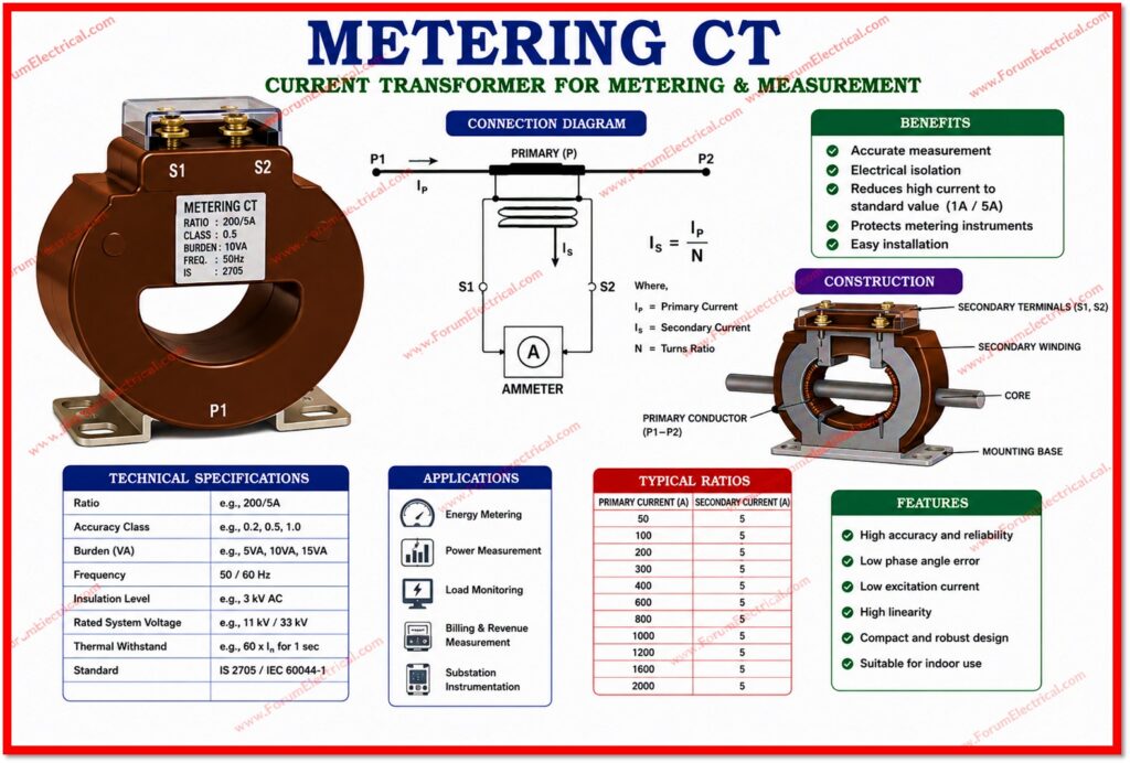
A metering CT is designed to provide accurate current measurement under normal operating conditions.
Its primary function is to feed
- Energy meters,
- Ammeters,
- Wattmeters and
- Other measuring instruments
so that utilities and consumers can accurately record the amount of electrical energy consumed.
Because billing and revenue depend directly on the accuracy of these readings, metering CTs are built to extremely tight accuracy tolerances within the normal load range.
A key characteristic of a metering CT is that its core is designed to saturate at relatively low levels of fault current.
This may result like a disadvantage but it is actually a protective feature: during a short circuit (or) fault condition the CT core saturates quickly & limits the secondary output.
This saturation protects the sensitive and often costly metering instruments and energy meters connected to the CT from being subjected to damaging high currents that would otherwise flow during a fault.
What is a Protection CT?
A protection CT, on the other hand, is designed with an entirely different priority: to remain accurate and deliver a proportional secondary current even during severe fault conditions, when the primary current may be ten to twenty times or more the rated current.
Protection CTs feed protective relays that are responsible for detecting abnormal conditions such as
- Overcurrent,
- Short circuits and
- Earth faults
and for initiating the circuit breaker tripping to isolate the faulty section of the network.
Since relays should operate reliably at high fault currents to clear faults quickly & prevent equipment damage (or) fire hazards, protection CTs are designed with a high knee point voltage & a high Accuracy Limit Factor (ALF).
This is because the primary core does not saturate easily & continues to generate the primary fault current accurately on the secondary side over a much wider current range compared to a metering CT.

Difference between Metering CT and Protection CT
Metering CT vs Protection CT
Key Differences
| Parameter | Metering CT | Protection CT |
|---|---|---|
| Primary Purpose | Accurate measurement of current for billing, energy metering and revenue purposes | Reliable operation of protective relays during fault/abnormal conditions |
| Accuracy Class | High accuracy at normal load (e.g. 0.2, 0.2S, 0.5, 0.5S) | Relatively lower accuracy requirement, but must remain linear at high fault currents (e.g. 5P, 10P) |
| Accuracy Range | Accurate only within normal working range, typically 5%–120% of rated current | Must stay accurate up to many times rated current, e.g. 10–20 times rated current |
| Behavior at Fault Current | Core saturates deliberately at high fault current to protect connected meters/instruments | Core must NOT saturate until a high multiple of rated current, so relay sees the true fault magnitude |
| Knee Point Voltage | Low knee point voltage (saturates early) | High knee point voltage (saturates late, if at all, within design limits) |
| Burden | Low burden, matched to meter/instrument requirement | Higher burden to accommodate relay coils and connected protection devices |
| Instrument Security Factor (ISF) / Accuracy Limit Factor (ALF) | Low ISF (typically less than 5), so the CT protects the meter by saturating early | High ALF (typically 10–30), so the CT continues to reproduce current accurately during faults |
| Core Material | High permeability core material for excellent accuracy at low current | Core designed for linearity over a wide current range without saturation |
| Standard Designations (IS/IEC) | Class 0.1, 0.2, 0.2S, 0.5, 0.5S, 1.0 | Class 5P10, 5P20, 10P10, 10P20, PS class |
| Typical Application | Energy meters, tariff metering, check metering, power quality analyzers | Overcurrent relays, differential relays, earth fault relays, distance protection |
| Connected Devices | kWh/kVArh meters, ammeters, voltmeters, wattmeters used for billing | Relays, trip circuits, protection IEDs, circuit breaker tripping systems |
| Response Time Requirement | Not time critical, must be accurate under steady, normal conditions | Must respond quickly and accurately during transient and fault conditions |

Accuracy Class and Related Terms
Accuracy Class (Metering CT)
The accuracy class of a metering CT such as 0.2, 0.5 (or) 1.0 indicates the maximum permissible percentage error at rated current.
A Class 0.2 CT, for example, guarantees an error of no more than 0.2 percent at rated current making it suitable for the revenue metering where financial accuracy is essential.
The ‘S’ suffix as in 0.2S or 0.5S indicates that the CT maintains its accuracy over an extended range from as low as 1% to 120% of rated current that is particularly useful for accurately billing loads that vary widely.
Accuracy Limit Factor & Class (Protection CT)
Protection CTs are rated using designations like 5P10 or 10P20. The first number indicates the composite error limit in percent at the accuracy limit current, while the letter P denotes protection class. The number following P such as 10 (or) 20 represents the Accuracy Limit Factor that means the CT remains accurate up to 10 (or) 20 times its rated current.
A CT rated 5P20, therefore, will have a composite error not exceeding 5 percent even when the fault current reaches 20 times the rated current, ensuring the connected relay receives a reliable signal to operate correctly.
PS Class CTs
For certain protection schemes particularly differential protection used in
- Transformers,
- Generators and
- Busbars
a special class known as PS Class (or) Protection Special is used.
PS Class CTs are defined by their
- Knee point voltage,
- Magnetizing current and
- Secondary winding resistance
rather than a simple accuracy limit factor that is allowing protection engineers to accurately calculate CT performance under complex fault conditions.
Why the Design Difference Important?
The contrasting design of metering and protection CTs directly serve their respective purposes.
If a metering CT were utilized for protection duties its early core saturation at fault current would prevent the relay from seeing the true magnitude of the fault current that is causing the relay to under read the fault & potentially fail to trip the breaker in time.
This could result in
- Prolonged fault duration,
- Increased equipment damage and
- Serious safety hazards.
Conversely if a protection CT were utilized for metering its lower accuracy class at normal load currents would result in billing errors, as protection CTs are not optimized for the fine accuracy needed at low & normal current levels.
Additionally protection CTs generally have a higher burden and larger core making them unnecessarily bulky & costly for pure metering applications.
Combined CTs for Metering and Protection
In many practical installations, especially in medium and low voltage panels, a single CT may have multiple secondary windings, or ‘cores,’ within the same housing, each dedicated to a specific function. For example, a CT might have one core wound for metering (Class 0.5S) and a second, separate core wound for protection (Class 5P20).
This arrangement allows both functions to be served from the same primary conductor while ensuring each core is optimized independently for its intended duty without one function compromising the performance of the other.
Practical Selection Guidelines
- Always confirm whether the application is for billing (or) metering for relay protection before specifying CT class.
- Use Class 0.2S (or) 0.5S CTs for revenue metering to assure the compliance with utility accuracy standards.
- Select an appropriate Accuracy Limit Factor (ALF) for the protection CTs based on the maximum expected fault current & relay setting requirements.
- For differential & busbar protection schemes evaluate the use of PS Class CTs with the proper knee point voltage calculations.
- Never interchange metering & protection CTs even temporarily as this can compromise billing accuracy (or) protection reliability.
- Verify the burden requirements for all connected instruments & relays to avoid CT saturation (or) accuracy degradation.
Conclusion
Metering CTs & protection CTs, while similar in basic construction, are engineered to fulfil distinctly different objectives within an electrical power system.
Metering CTs prioritize high accuracy at normal load levels to ensure fair & accurate billing, deliberately sacrificing performance during fault conditions to protect connected instruments.
Protection CTs are built to remain accurate and linear at high fault currents ensuring that protective relays can detect faults & initiate timely tripping to protect equipment and personnel.
A detailed understanding of differences between Metering CT & Protection CT along with correct selection based on
1). Accuracy class,
2). Burden & accuracy limit factor
is essential for designing safe, reliable & efficient electrical distribution & protection systems.

