")
Electricity meters in residential, commercial & industrial systems must be calibrated to accurately accurately measure and log energy consumption.
- What is Energy Meter Calibration?
- Scope
- Equipment Required
- Standards & Compliance
- Calibration Procedure
- Phase-1: Pre-Calibration Preparation
- Step-1: Meter Documentation & Initial Inspection
- Step-2: Establish Environmental Conditions
- Step-3: Prepare Calibration Equipment
- Step-4: Safety Verification
- Phase-2: Test Setup and Configuration
- Step-5: Circuit Configuration & Meter Connection
- Step-6: Equipment Calibration & Verification
- Phase-3: Load Test & Measurement
- Step-7: No Load Test
- Step-8: Multiple Load Points Testing
- Step-9: Power Quality Assessment
- Step-10: Extended Duration Test
- Phase-4: Data Analysis and Verification
- Step-11: Error Analysis & Tolerance Verification
- Step-12: Power Quality Impact Assessment
- Step-13: Retest if Adjustments are Executed
- Energy Meter Calibration Test Results
- Checklist
- Calculator
Meter readings are used for invoicing, energy auditing & regulatory compliance, therefore even minor errors can cause financial losses, disputations and legal complications.
Modern calibration goes beyond kWh accuracy checks due to energy efficiency, smart grids and power quality.
Technicians can assess
- Active power,
- Reactive power,
- Harmonics,
- Power factor,
- Voltage quality and
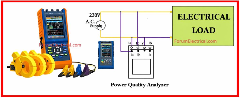
- Meter accuracy with Megger Power Quality (PQ) Analyzers.
This post covers energy meter calibration using modern Megger PQ analyzer methods that meet international standards.
What is Energy Meter Calibration?
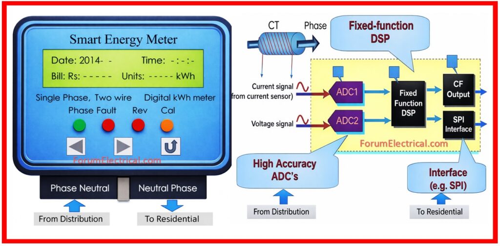
Energy meter calibration compares an electricity meter readings to a recognized reference standard under controlled settings to verify its accuracy.
To verify that the meter functions within accuracy limitations under various load & power factor conditions.
Calibration measures meter performance, aging and measurement variation, unlike routine inspections.
Power quality assessment in modern calibration ensures that harmonics, voltage distortion and frequency changes do not affect meter accuracy.
Scope
Energy meter calibration provides accurate energy measurement for appropriate billing and revenue preservation.
It identifies energy losses, enhances energy audits & improves planning and load management data.
Calibrating meters is required by IEC standards (IEC 62052-11 and IEC 62053) and allows predictive maintenance to detect performance losses.
Equipment Required
1). Megger PQ Analyzer
2). Wattmeter
3). Power Source and Load Bank
4). CTs and PTs
5). Test Leads and Connectors
6). Digital Multimeter & Clamp Meter
7). Calibration Software
8). Environmental Monitoring Tools
9). Safety Equipment
10). PPE
Standards & Compliance
- IEC 62052-11: General Metering Requirements
- IEC 62053-21: Accuracy Classes
- ISO 6379: Calibration traceability
- National regulatory standards.
Calibration Procedure
Phase-1: Pre-Calibration Preparation
Step-1: Meter Documentation & Initial Inspection
Record all meter information including the
Manufacturer:
Model number:
Serial number:
Accuracy class:
Rated voltage:
Rated current:
Calibration date:
History:
Note the meter’s lifespan and past servicing conditions.
Visually inspect the meter for any physical damage, corrosion (or) exposure to the environment that might reduce accuracy.
Check for seal integrity & tamper indicators. Take illustrations of the meter for documentation.
Check that the meter fulfills the work order specifications & the proposed test procedure.
Step-2: Establish Environmental Conditions
Measure and record the ambient temperature, humidity and air pressure.
Ensure the calibration environment satisfies standard conditions (23°C ± 5°C, humidity 45-75% RH) and document any differences for result interpretation.
Allow the meter to settle in the test conditions for at least 30 minutes before starting measurements.
Record and measure basic meter readings to establish a baseline.
Step-3: Prepare Calibration Equipment
Ensure that the Megger PQ analyzer along with all reference devices have current calibration certificates from approved laboratories.
Perform self-check protocols on the PQ analyzer to verify good operation.
Configure calibration software with the necessary test parameters, meter specifications and tolerance limitations.
Check the calibration technique unique to the meter type being tested.
Inspect all wires and connectors for damage (or) wear.
Step-4: Safety Verification
Check that the isolation transformers alongside safety interlocks work properly.
Ensure that emergency shut-off switches are accessible.
Inform all personnel about electrical hazards & emergency procedures.
Confirm the availability of first-aid supplies & emergency contact information.
Phase-2: Test Setup and Configuration
Step-5: Circuit Configuration & Meter Connection
Single Phase Meter
For single-phase meters, connect them in series with the power source via the current path with the voltage connected via the supply terminals.
Three Phase Meter
For three-phase meters, make proper three-phase connections with CT and PT configurations that fit the meters specifications.
To monitor reference readings simultaneously, connect the Megger PQ analyzer in parallel with test meter.
Ensure that all connections are secure & appropriately insulated.
Use proper gauges of test leads to reduce contact resistance.
Step-6: Equipment Calibration & Verification
Use a normal wattmeter (or) a Megger PQ analyzer in parallel setup to establish the reference measurement.
Note the reference readings for voltage, current, frequency, power factor & active power.
Perform zero-load verification to establish a baseline accuracy.
Test the data logging system to confirm that all parameters are properly recorded.
Check that the test meter display is accessible & the readings are apparent.
Phase-3: Load Test & Measurement
Step-7: No Load Test
With the test circuit turned on but no load applied, take readings from both of the test meter and the reference instruments.
This test confirms correct meter energization & baseline accuracy at zero power levels.
Step-8: Multiple Load Points Testing
Perform systematic tests at the standardized load levels of 10%, 25%, 50%, 75% and 100% rated current.
At each load point, keep conditions steady for at least 2-3 minutes.
Take simultaneous readings from the test meter & the reference equipment.
Use the following formula to calculate the percentage inaccuracy at each load point:
Error % = [(Test Meter Reading – Reference Reading) / Reference Reading] x 100
Record the test conditions at each load point, including voltage, frequency and ambient temperature.
Test three-phase meters under various power factor settings (unity power factor, trailing power factor at 0.8 and leading power factor at 0.8).
Step-9: Power Quality Assessment
The Megger PQ analyzer can be used to assess harmonic content, voltage distortion, current distortion and power quality parameters.
Calculate the total harmonic distortion (THD) of voltage & current. Record any voltage sags, swells (or) frequency changes.
This information contributes in determining if poor meter accuracy is caused by meter faults (or) power quality concerns affecting the installation.
Step-10: Extended Duration Test
For important applications, run an extended 30-60 minute test under nominal operating conditions.
Take continual measurements to detect any thermal drift (or) performance changes over time.
This test identifies potential reliability concerns that were not apparent via short-duration testing.
Phase-4: Data Analysis and Verification
Step-11: Error Analysis & Tolerance Verification
Compare the measured errors at each load point to the appropriate tolerance limits.
Class 1 Meters: Class 1 meters typically have permissible error limits ranging from -0.5% to +0.5%.
Class 2 Meters: Class 2 meter limits usually range from -1% to +1%. Calculate the average error for all load points.
Determine whether any single load point exceeding tolerance limits.
Create an error curve demonstrating how accuracy varies with the load conditions.
Step-12: Power Quality Impact Assessment
Determine whether power quality distortions (harmonics and voltage fluctuations) have a significant impact on meter accuracy.
Determine whether the reported errors are associated with harmonic conditions (or) other power quality issues.
Document any conditions outside of the meter that may affect measurement accuracy.
Step-13: Retest if Adjustments are Executed
If meter modifications are made (for analog meters with the adjustment provisions) test at all load points to ensure that the calibration corrections are effective.
Confirm that the adjusted meter is now operating within acceptable tolerance limits across the whole load range.
Energy Meter Calibration Test Results
Accuracy Assessment
Accuracy assessment involves expressing calibration results as percentage (or) absolute error (kWh).
Class 1 meters have errors of ±0.5% at all test sites while Class 2 meters might have errors ranging from ±1% to ±2% depending on regulatory approval.
Load-Dependent Error Patterns
A consistent error across all load levels shows a systematic offset which can be adjusted.
Errors that grow with load show nonlinearity caused by component age (or) saturation but irregular errors frequently indicate loose connections, CT/PT ratio difficulties (or) internal meter failures.
Power Quality Effects
High harmonic distortion can reduce meter accuracy particularly in older (or) mechanical meters.
Modern digital meters are more tolerant but THD exceeding 5% or voltage variations beyond ±10% of nominal necessitate additional study.
Certification & Compliance
Meters that meet specified tolerance levels are certified and regarded compliant for a set validity term (usually up to two years).
Meters that exceed their limitations must be adjusted (if possible) (or) removed from operation and digital meters are normally replaced whereas adjustable analog meters can be recalibrated.
Checklist
Calculator
Energy meter calibration is essential for correct billing, regulatory compliance and efficient energy management.
By integrating regular calibration procedures with modern PQ analyzers, utilities and industry may maintain measurement accuracy, detect power quality issues and protect the sources of revenue.
