What is an Inductive Proximity Sensor?
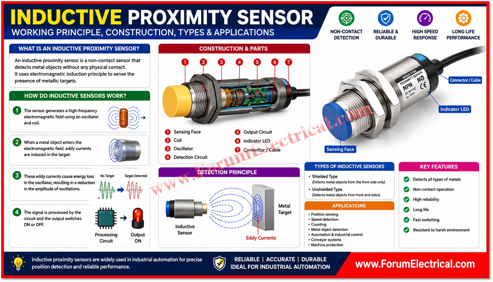
An inductive proximity sensor is a non contact electronic device used to detect the presence, absence (or) position of metallic objects without any physical touch between the sensor and the target.
- What is an Inductive Proximity Sensor?
- Main Components of an Inductive Proximity Sensor
- Working Principle of an Inductive Proximity Sensor
- Sensing Distance and Correction Factors
- Shielded vs. Unshielded Types
- 1). Shielded (Flush-Mountable) Sensors
- 2). Unshielded (Non-Flush) Sensors
- Output Types & Wiring Configurations
- 1). NPN (Sinking Output)
- 2). PNP (Sourcing Output)
- Key Features of an Inductive Proximity Sensor
- Typical Specifications of an Inductive Proximity Sensor
- Selecting the Right Sensor
- Advantages of an Inductive Proximity Sensor
- Applications of an Inductive Proximity Sensor
- Conclusion
It works by generating a high frequency electromagnetic field at its sensing face and continuously monitoring that field for disturbances caused by nearby metal.
Because of its contactless operation, fast response and rugged construction, the inductive proximity sensor is considered one of the most dependable and widely deployed sensing technologies in modern industrial automation.
Unlike mechanical limit switches which depends on physical actuation and are prone to wear, inductive proximity sensors contain no moving parts.
This absence of mechanical contact translates directly into higher reliability that has a longer operational lifespan & consistent performance even under harsh industrial conditions such as dust, oil mist, vibration & moisture.
As a result, these sensors have become a default choice wherever fast, repeatable and maintenance free metal detection is required.
This post provides a detailed technical explanation of how inductive proximity sensors work, the internal components that make detection possible, the different mounting and output configurations availability, key specifications to consider during selection and the wide variety of industries and machines in which these sensors are used.
Main Components of an Inductive Proximity Sensor
An inductive proximity sensor is built from several functional blocks that work together to create the electromagnetic field that detect changes caused by a metal target and convert that change into a usable electrical output.
Each of these components plays an important function in the overall detection procedure.
| S.No | Component | Function |
| 1 | Sensing Face | The active front surface of the sensor that houses the coil & radiates the electromagnetic field used to detect nearby metal objects. Material and form affect detecting distance. |
| 2 | Oscillator Circuit | Creates a consistent & high frequency alternating current which drives the sensing coil to give the electromagnetic field needed for detection. |
| 3 | Coil (Ferrite Core) | The ferrite-cored coil radiates and forms magnetic fields. The ferrite core improves sensitivity by focusing the field on the sensing face. |
| 4 | Demodulator Circuit | Continuously monitors the amplitude of the oscillator signal & detects the small reduction caused by eddy current losses when a metal target enters the field. |
| 5 | Trigger / Schmitt Circuit | Converts the smooth, continuously varying demodulator signal into a clean, noise free digital switching signal with defined ON and OFF thresholds (hysteresis). |
| 6 | Output Circuit (NPN/PNP) | Converts the detected signal into a switching output compatible with PLCs, relays (or) industrial controllers, using either NPN or PNP transistor stages. |
| 7 | Status LED | Provides a visual indication of the sensors switching state, allowing technicians to verify operation without external test equipment. |
| 8 | Housing | Depending on IP rating and chemical resistance, nickel-plated brass, stainless steel or PBT plastic encloses and protects internal wiring. |
| 9 | Cable or Connector | Supplies DC power to the sensor and carries the switching output signal back to the control system, typically via a 2-wire, 3-wire (or) 4-wire configuration. |
Working Principle of an Inductive Proximity Sensor
The detection process of an inductive proximity sensor is based on electromagnetic induction and eddy current losses.
It occurs in a continuous, repeating cycle as follows:
- The oscillator circuit energizes the sensing coil that is creating a high-frequency alternating electromagnetic field that radiates outward from the sensing face.
- When a metallic object enters this electromagnetic field circulating eddy currents are induced on the surface of the target in accordance with Faraday’s law of electromagnetic induction.
- These eddy currents generate their own opposing magnetic field which draws energy away from the sensors oscillator circuit that is causing a measurable reduction (damping) in oscillation amplitude.
- The demodulator circuit continuously tracks the oscillators amplitude & detects this damping effect as the target approaches.
- Once the amplitude drops below a predefined threshold the trigger circuit changes state generating a sharp & clean digital transition rather than a gradual analog change.
- The output circuit then switches the sensors electrical output ON (or) OFF (depending on NO or NC configuration), signaling the presence (or) absence of the metal target to the connected PLC (or) controller.
This entire sequence, from field disturbance to output switching which typically occurs within microseconds which is why inductive proximity sensors can attain switching frequencies of several kilohertz.
This makes them well suited to high-speed counting, indexing and positioning tasks on fast moving production lines.
The sensing distance depends heavily on the electrical conductivity and magnetic permeability of the target material.
Ferromagnetic metals such as mild steel typically produce the strongest response and the longest rated sensing distance while non-ferrous metals such as aluminum, brass and copper produce weaker eddy currents and therefore shorter effective sensing distances that is often expressed using a correction factor relative to a mild steel reference target.
Sensing Distance and Correction Factors
Sensing Distance
Manufacturers specify the sensing distance of an inductive proximity sensor using a standard mild steel target of a defined size.
Correction Factors
When the actual target material differs a correction factor should be applied to estimate the real world sensing distance. Typical correction factors that is expressed as a percentage (%) of the rated sensing distance are shown below:
| Target Material | Approximate Correction Factor |
| Mild Steel (reference) | 100% |
| Stainless Steel | 60-80% |
| Brass | 35-50% |
| Aluminium | 30-45% |
| Copper | 25-40% |
Beyond target material other factors that influence sensing distance include target size & thickness relative to the sensing face diameter, target alignment (a target should approach the sensing face straight-on for best accuracy), ambient temperature and supply voltage stability.
Shielded vs. Unshielded Types
Inductive proximity sensors are also classified by how their electromagnetic field is shaped which determines how they should be mounted.
1). Shielded (Flush-Mountable) Sensors
In shielded sensors, a metal ring surrounds the ferrite core and coil focusing the electromagnetic field directly forward from the sensing face.
This containment allows the sensor body to be mounted flush with surrounding metal without triggering false detection but it typically results in a shorter maximum sensing distance compared to an unshielded version of the same size.
2). Unshielded (Non-Flush) Sensors
Unshielded sensors have no surrounding metal ring allowing the electromagnetic field to radiate outward from the sides as well as the front.
This generates a longer sensing distance but the sensor should be mounted with clear space around the sensing face to avoid surrounding metal from causing false triggering.
Output Types & Wiring Configurations
1). NPN (Sinking Output)
An NPN sensor switches the output to 0 V (ground) when activated.
The load is connected between the positive supply and the sensor output terminal and current flows into the sensor when triggered.
NPN sensors are commonly used in Asian automation systems and in applications where the control systems inputs are wired to sink current.
2). PNP (Sourcing Output)
A PNP sensor switches the output to the positive supply voltage (+VDC) when activated.
The load is connected between the sensor’s output terminal and ground and current flows out of the sensor when triggered.
PNP sensors are widely used in European automation systems and are generally considered safer for troubleshooting since a short circuit to ground is easier to detect than a short to the positive rail.
Both NPN and PNP sensors are available in Normally Open (NO) and Normally Closed (NC) variants:
- Normally Open (NO): The output is OFF in the absence of a target & switches ON when a metal object is detected.
- Normally Closed (NC): The output is ON in the absence of a target & switches OFF when a metal object is detected.
Sensors are also available in 2-wire, 3-wire and 4-wire configurations.
Two-wire sensors are wired in series with the load and are simple to install but have a small voltage drop and leakage current.
Three-wire sensors provide separate power, ground and output lines giving more reliable switching.
Four-wire sensors add a second output allowing both NO and NC signals to be available simultaneously from the same unit.
Key Features of an Inductive Proximity Sensor
- Non contact detection with no mechanical wear.
- Detects ferrous and non ferrous metals.
- High switching speed up to several kHz.
- Long service life due to solid-state construction.
- Resistant to dust, oil, vibration and moisture.
- Excellent reliability in harsh industrial environments.
- Maintenance free operation at once it is installed.
- Compact form factors for easy integration into a tight spaces.
Typical Specifications of an Inductive Proximity Sensor
| Parameter | Typical Value |
| Operating Voltage | 10 – 30 VDC |
| Sensing Distance | 2 – 40 mm (model dependent) |
| Switching Frequency | Up to 5 kHz |
| Repeatability | Typically ≤ 5% of rated sensing distance |
| Hysteresis | 1 – 15% of sensing distance (prevents output chatter) |
| Operating Temperature | -25°C to +70°C |
| Protection Rating | IP67 or higher (model dependent) |
| Housing Material | Nickel-plated brass, stainless steel (or) PBT plastic |
| Output Current Rating | Typically 100 – 200 mA |
Selecting the Right Sensor
Choosing the correct inductive proximity sensor for an application involves evaluating several factors together rather than depending on a single specification.
The following points summarize the primary selection criteria used by automation engineers:
- Required sensing distance and available mounting space (shielded vs. unshielded).
- Target material and its correction factor relative to mild steel.
- Required switching frequency for the speed of the application.
- Required output type (NPN/PNP) to match original PLC input cards.
- Temperature, washdown need and chemical exposure determine IP rating and housing material.
- Connector type and cable length required for the installation.
Advantages of an Inductive Proximity Sensor
- No physical contact with the target that is eliminating mechanical wear.
- High accuracy and repeatability across millions of switching cycles.
- Fast response time suitable for high-speed automation.
- Immune to dirt, oil and dust that would foul optical sensors.
- Low maintenance requirements once installed and calibrated.
- Long operational life due to solid-state & contactless design.
- Reliable performance across a wide range of harsh industrial conditions or environments.
Applications of an Inductive Proximity Sensor
- Conveyor object detection.
- Machine automation and interlocking.
- PLC based control systems.
- Position and end of travel sensing.
- Limit detection on cylinders & actuators.
- Part counting on the production lines.
- Packaging machines.
- CNC machines & tool detection.
- Robotic systems.
- Material handling equipment.
Conclusion
Inductive proximity sensors are still relied on in industrial automation.
Their non-contact operation, reliability and protection from harsh environmental conditions make them ideal for continuous factory operation.
Electromagnetic field creation, eddy current induction & amplitude demodulation enable quick, accurate & maintenance-free metal detection.
Engineers and technicians may choose and use the right sensor for almost any metal-detection task by understanding the internal components, target material’s effect on sensing distance, shielded vs. unshielded designs and output configurations.
From simple conveyor object recognition to accurate positioning in robotic and CNC systems, inductive proximity sensors will underpin reliable industrial automation.

