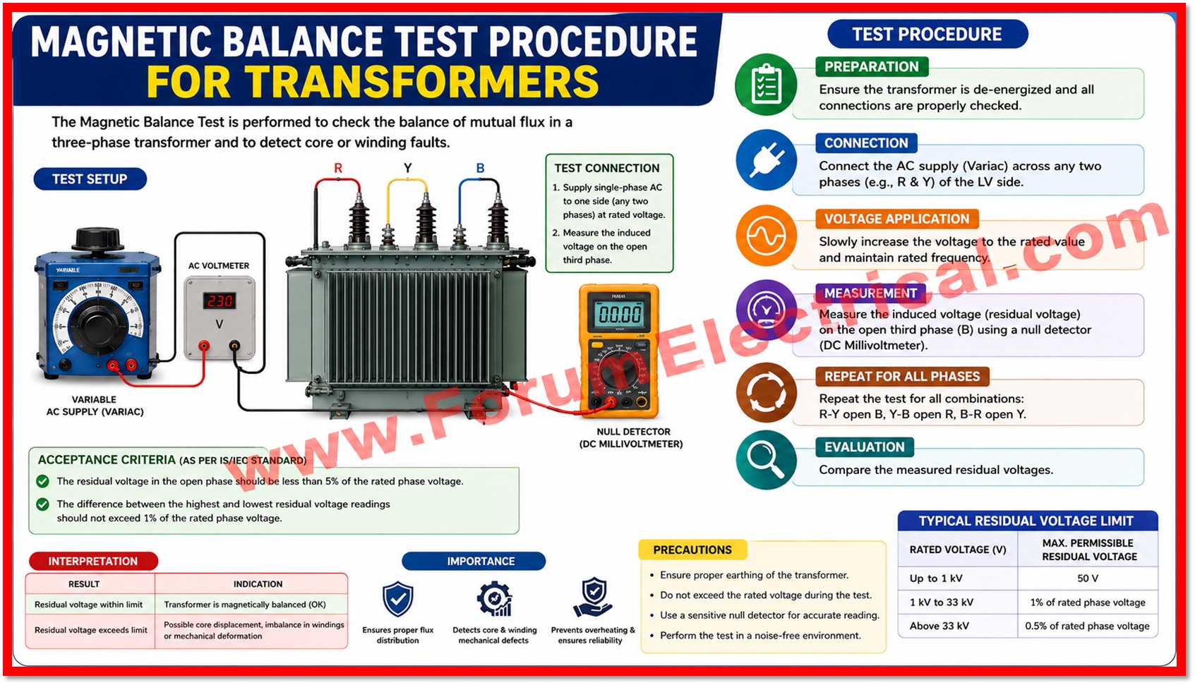
This Method of Statement (MOS) describes the safe working procedure and technical methodology for conducting the Magnetic Balance Test on the power and distribution transformers prior to energization (or) as part of periodic/commissioning electrical testing.
Purpose
The test verifies the integrity and symmetry of the transformer magnetic circuit and confirms the absence of inter turn short circuits (or) winding faults on the High Voltage (HV) and where applicable, the intermediate (XV) and tertiary (YV) windings.
Scope
This procedure applies to all power and distribution transformers undergoing commissioning tests, periodic maintenance tests (or) post-repair verification tests at site prior to connection to
- Upstream (or) downstream cables,
- Bus bars or
- Switchgear.
The scope covers isolation requirements, safety precautions, test equipment, step-by-step test procedure, acceptance criteria and documentation of results for the Magnetic Balance Test conducted in accordance with IEC 60076.
Reference Standards and Documents
- IEC 60076-1: Power Transformers – General
- IEC 60076 (applicable parts) – Test procedures for power transformers
- IEEE C57.152-2013 – Guide for Diagnostic Field Testing of Fluid-Filled Power Transformers
- CIGRE Technical Brochure TB445 – Guide on Transformer Intelligent Condition Monitoring
- Manufacturers Type Test Certificates and Approved Drawings
- Project-specific Inspection and Test Plan (ITP)
Safety Precautions
- Obtain a valid Permit to Work (PTW) prior to commencement of the test activities.
- Before starting the test, disconnect & ground all HV, XV & YV bushing terminal linkages & isolate the transformer from all upstream and downstream connections.
- Use an approved voltage detector to confirm de-energized condition & used to apply temporary earths according to site earthing procedures.
- Protect the test area & display suitable warning signs.
- Ensure all test staff wear proper personal protective equipment (PPE) such as insulated gloves, safety helmets & footwear.
- Use calibrated equipment that have only valid calibration certificate.
- Discharge all windings to earth before & after each test utilizing a discharge rod.
- Do not touch any winding terminal while the supply is energised; switch off & discharge before making (or) altering connections.
Test Equipment Required
| S.No | Equipment / Instrument | Remarks |
| 1 | 3-Phase AC Supply Source (415 V AC) | Calibrated |
| 2 | Single Phase AC Supply Source (230 V AC) | Calibrated |
| 3 | Digital / Analog AC Voltmeters | Calibrated & valid certificate |
| 4 | Test / Jumper Leads and Connectors | Rated for test voltage |
| 5 | Earthing Rods and Discharge Sticks | Safety equipment |
| 6 | Personal Protective Equipment (PPE) | Helmet, gloves & safety shoes |
Pre-Test Requirements
Prior to commencing the Magnetic Balance Test the following conditions shall be verified and confirmed:
- The transformer and all HV, XV and YV winding bushing terminal links are isolated (disconnected) from upstream & downstream connections and are grounded.
- Both the primary and secondary windings are confirmed free from any connection to cables (or) bus bars.
- Oil level, gaskets & external condition of the transformer have been visually inspected & found satisfactory.
- No parallel test activity (e.g. Insulation Resistance / Winding Resistance test) is in progress on the same winding.
- No specific pre-conditioning (or) pre-check of the transformer is required prior to this test.
Test Procedure
Magnetic Balance Test
The Magnetic Balance Test is conducted to check for imbalance in the transformers magnetic circuit.
Normal Condition
Under healthy conditions, the sum of the induced voltages in the 2 unexcited limbs will approximately equal the voltage measured across the excited winding.
Fault Condition
Any significant deviation from this balance may indicate an inter-turn short circuit (or) other winding fault.
The test is generally performed on the HV winding (1U, 1V, 1W terminals) using a low voltage single-phase (or) three-phase AC supply as follows:
- Ensure that both the Primary (HV) and Secondary (LV) windings are completely disconnected from any external cables (or) bus bars.
- Apply a three-phase supply voltage of 415 V AC (or single-phase 230 V AC, as applicable) across terminals 1U and 1V and measure the corresponding induced voltages across 1U-1V, 1V-1W and 1U-1W.
- Switch off the supply, discharge the windings and repeat the test by applying the voltage across terminals 1V and 1W. Measure & record the corresponding voltages across 1U-1V, 1V-1W and 1U-1W.
- Switch off the supply, discharge the windings, and repeat the test a third time by applying the voltage across terminals 1U and 1W. Measure and record the corresponding voltages across 1U-1V, 1V-1W and 1U-1W.
- Observe & record all readings in the prescribed Test Record Format.
- Switch off and safely discharge the supply upon completion of all 3 test sequences.
Connection Reference
The table below summarizes the terminal pairs across which the test supply is applied and the corresponding terminal pairs at which the resulting voltages are measured for each stage of the test.
| Supply Applied Across | Terminals Measured | Winding Reference |
| 1U – 1V | 1U-1V, 1V-1W, 1U-1W | HV Winding |
| 1V – 1W | 1U-1V, 1V-1W, 1U-1W | HV Winding |
| 1U – 1W | 1U-1V, 1V-1W, 1U-1W | HV Winding |
Test set-up (typical): A regulated 415 V AC 3-phase (or 230 V AC single-phase) supply is connected through a suitably rated ammeter and switch to the HV bushing terminals of the transformer under test (1U, 1V, 1W). Voltmeters are connected across the respective terminal pairs to record the induced voltages during each stage of energization as summarized in the table above.
Acceptance Criteria
The transformer magnetic circuit is considered to be in a satisfactory and balanced condition if the sum of the two lower induced voltages is approximately equal, within ±5% to the third (higher) measured voltage in each test sequence.
Any deviation beyond this tolerance shall be investigated further & reported to the site engineer/client representative prior to proceeding with subsequent tests.
Test Record Format
All readings shall be recorded in the format below duly signed by the testing engineer & countersigned by the client/consultant representative.
| Sl. No | Voltage Applied Across | V (1U-1V) Volts | V (1V-1W) Volts | V (1U-1W) Volts | Result |
| 1 | 1U – 1V | ||||
| 2 | 1V – 1W | ||||
| 3 | 1U – 1W |
Documentation & Reporting
- Record all test data, ambient temperature and humidity at the time of testing.
- Attach calibration certificates of instruments utilized as an annexure to the test report.
- Obtain joint sign-off from the testing agency & client/consultant representative on the test format.
- Any abnormal observation shall be highlighted separately with recommended corrective action.
Conclusion
The Magnetic Balance Test when carried out in accordance with the procedure outlined above and referenced standards (IEC 60076, IEEE C57.152-2013, CIGRE TB445) provides a reliable preliminary check on the health of the transformer magnetic circuit and winding integrity prior to energization.
Satisfactory results with other routine electrical tests such as Insulation Resistance, Winding Resistance and Turns Ratio tests provide confidence that the transformer is fit for safe energization and service.

