What is a Gas Insulated Bus (GIB)?
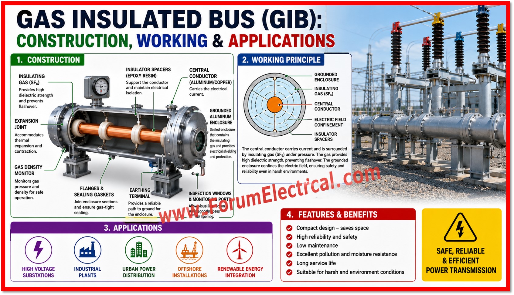
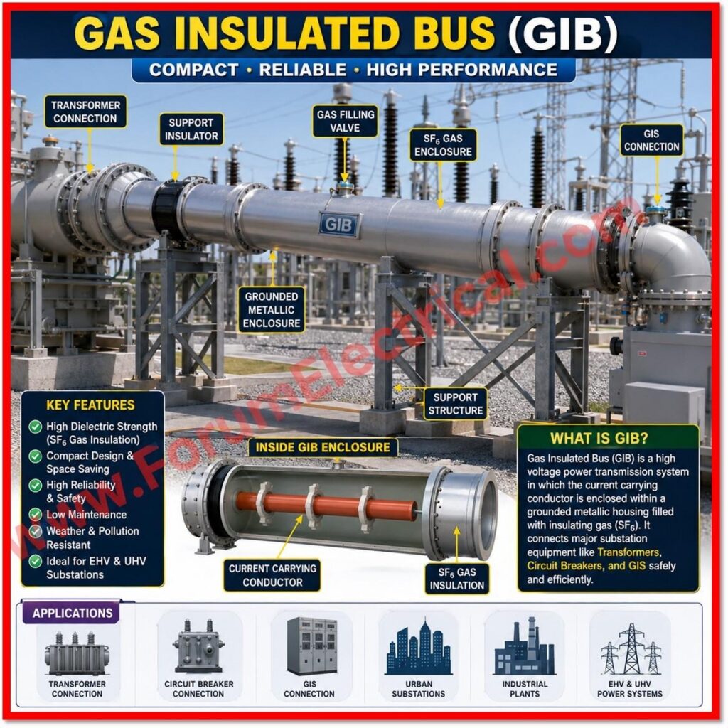
A Gas Insulated Bus is commonly abbreviated as (GIB) is a high voltage (HV) power transmission arrangement in which the current carrying conductor is enclosed within a grounded metallic housing that is filled with an insulating gas.
- What is a Gas Insulated Bus (GIB)?
- Primary Components
- Working Principle of Gas Insulated Bus (GIB)
- Typical Voltage Ratings of GIB
- Safety Precautions
- Common Tests
- Advantages of Gas Insulated Bus (GIB)
- Disadvantages of Gas Insulated Bus (GIB)
- Applications of Gas Insulated Bus (GIB)
- Difference between GIB and AIB
- Comparison: GIB vs. Air Insulated Bus (AIB)
- Conclusion
GIB systems form an important link between major parts of substation equipment such as
- Transformers,
- Circuit breakers and
- Gas insulated switchgear (GIS)
enabling the safe and compact transfer of large amounts of electrical power at extra high voltage (EHV) & ultra high voltage (UHV) levels.
Unlike conventional air insulated busbars which depend on the dielectric strength of open air & therefore need significant clearance distances, GIB confines the electric field within a sealed enclosure.
This allows substations to be designed with a dramatically reduced footprint while simultaneously improving reliability, safety and resistance to environmental contamination.
As power systems continue to expand and land availability in urban and industrial areas becomes increasingly constrained, GIB technology has become indispensable for modern substation design.
Primary Components
A GIB system is composed of many engineered components that work together to ensure safe and efficient power transmission.
Each component functions as an essential feature in maintaining electrical integrity, mechanical stability and long-term reliability of the installation.
Aluminum (or) Copper Conductor
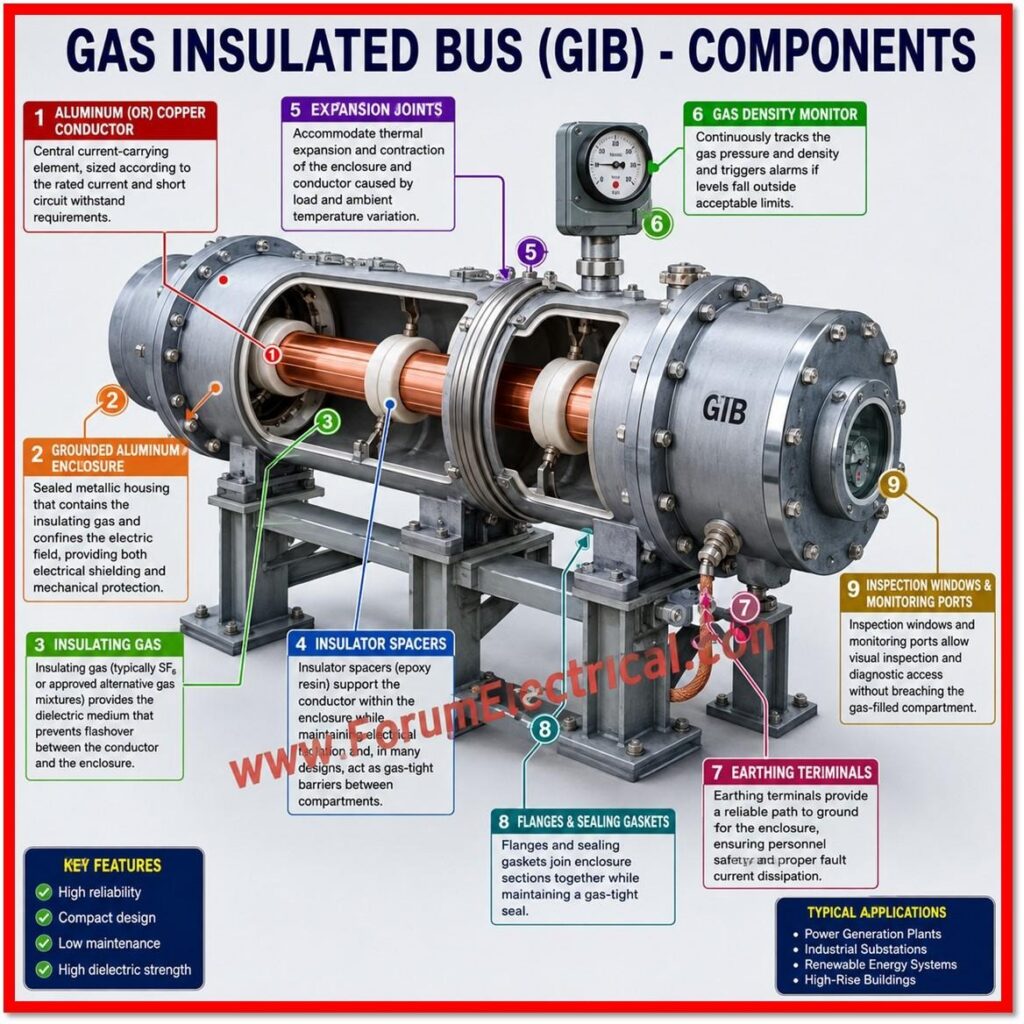
Aluminum (or) Copper Conductor is a central current-carrying element, sized according to the rated current and short circuit withstand requirements.
Grounded Aluminum Enclosure
A grounded aluminum enclosure is a sealed metallic housing that contains the insulating gas and confines the electric field providing both electrical shielding and mechanical protection.
Insulating Gas
Insulating gas (typically SF6 or approved alternative gas mixtures) provides the dielectric medium that prevents flashover between the conductor and the enclosure.
Insulator Spacers
Insulator spacers (epoxy resin) support the conductor within the enclosure while maintaining electrical isolation and, in many designs act as gas-tight barriers between compartments.
Expansion Joints
Expansion joints accommodate thermal expansion and contraction of the enclosure and conductor caused by load and ambient temperature variation.
Gas Density Monitor
The gas density monitor continuously tracks the gas pressure and density that is triggering alarms if levels fall outside acceptable limits.
Earthing Terminals
Earthing terminals give a reliable path to ground for the enclosure ensuring personnel safety & proper fault current dissipation.
Flanges & Sealing Gaskets
Flanges & sealing gaskets join enclosure sections together while maintaining a gas tight seal.
Inspection Windows & Monitoring Ports
Inspection windows & monitoring ports that allow visual inspection and diagnostic access without breaching the gas filled compartment.
Working Principle of Gas Insulated Bus (GIB)
The operating principle of a Gas Insulated Bus (GIB) is simple yet highly effective.
Electrical current flows through the central conductor which is precisely centered within the enclosure using epoxy resin spacers.
The surrounding insulating gas, pressurized within the sealed enclosure provides a high dielectric strength that prevents flashover (or) arcing between the energized conductor and the grounded enclosure wall.
The grounded metal enclosure serves a dual purpose.
Electrically, it confines with the electric field generated by the conductor which is minimizing electromagnetic interference with nearby equipment & personnel.
Physically, it forms a robust barrier that protects the conductor from dust, moisture, airborne pollutants, small animals and accidental human contact.
Because the entire assembly is sealed, the internal insulation performance remains largely unaffected by external weather conditions which is a key reason GIB is favored in coastal, polluted and humid environments.
Typical Voltage Ratings of GIB
GIB systems are manufactured and type tested for a standard range of voltage classes to suitable various transmission and distribution applications:
| Voltage Class |
|---|
| 72.5 kV |
| 145 kV |
| 245 kV |
| 420 kV |
| 550 kV |
| 765 kV |
Safety Precautions
Given the high voltages (HV) and pressurized gas systems involved strict safety precautions must be observed throughout installation, operation & maintenance:
- Verify the gas pressure before energization.
- Ensure a proper earthing before maintenance.
- Monitor the gas density alarms regularly.
- Utilize calibrated gas handling equipment.
- Follow the lockout/tagout (LOTO) procedures.
- Wear appropriate personal protective equipment (PPE) during any testing and maintenance.
Common Tests
A comprehensive testing is essential to verify the integrity and performance of a GIB installation, both during factory acceptance and after site erection.
Typical tests include:
| Test | Purpose |
|---|---|
| Visual inspection | Confirms correct assembly, absence of physical damage and proper alignment. |
| Gas pressure and density check | Verifies gas fill meets rated specification for the dielectric performance. |
| Gas leakage test | Detects and locates any leaks in flanges, seals (or) enclosure joints. |
| Dew point (moisture) measurement | Ensures moisture content within the gas remains within safe limits. |
| Insulation resistance (IR) test | Confirms adequate resistance between conductor & enclosure. |
| AC withstand voltage test | Validates the system can withstand rated overvoltage without any flashover. |
| Partial discharge (PD) test | Detects incipient insulation defects before they develop into failures. |
| Contact resistance measurement | Confirms low resistance joints at conductor connections. |
| Mechanical inspection | Checks support structures, expansion joints and flange torque. |
| Earthing continuity test | Verifies a reliable low resistance ground path for the enclosure. |
Advantages of Gas Insulated Bus (GIB)
- Compact design, significantly reducing substation footprint.
- High reliability under continuous operating conditions.
- Excellent insulation performance across the varying load conditions.
- Minimum maintenance requirements compared to open air systems.
- Suitable for polluted, coastal and humid environments.
- High personnel safety due to fully enclosed live parts.
- Long service life with proper maintenance.
- Weatherproof construction suitable for both outdoor & underground installation.
- Low electromagnetic interference (EMI) with adjacent equipment.
Disadvantages of Gas Insulated Bus (GIB)
- Higher initial capital cost (initial investment) compared to air insulated alternatives.
- Needs specialized installation & commissioning testing.
- Continuous gas leakage monitoring is necessary.
- Repairs & troubleshooting are more complex than for air-insulated busbars.
Applications of Gas Insulated Bus (GIB)
GIB systems are deployed across a wide range of power system installations including:
- GIS substations,
- Power plants,
- Solar power evacuation substations,
- Wind power substations,
- Hydroelectric stations,
- Underground substations,
- Industrial power distribution and
- Extra High Voltage (EHV) and Ultra High Voltage (UHV) systems.
Difference between GIB and AIB
Comparison: GIB vs. Air Insulated Bus (AIB)
While both GIB and Air Insulated Bus (AIB) systems serve the same fundamental purpose of conducting current across substation equipment they differ significantly in construction & performance characteristics.
The table below summarizes the key differences.
| Parameter | Gas Insulated Bus (GIB) | Air Insulated Bus (AIB) |
|---|---|---|
| Insulation | Gas insulated (SF6 or alternative gas) | Air insulated |
| Space required | Very low | High |
| Reliability | Very high | Moderate |
| Maintenance | Low | Higher |
| Pollution resistance | Excellent | Lower |
| Initial cost | Higher | Lower |
| Safety | Higher | Moderate |
Conclusion
In modern high voltage substations, gas insulated bus technology is a compact, dependable and safe alternative to air insulated busbars.
GIB systems superior insulation, low maintenance and environmental degradation resistance make them ideal for polluted, coastal, humid and space constrained sites like underground substations as well as renewable energy evacuation stations.
GIB is becoming more popular for EHV and UHV transmission networks worldwide due to its reliability, safety and reduced footprint despite its higher initial investment and need for specialized installation, testing & gas leakage monitoring.
The development of SF6 alternative gas mixes is intended to make GIB technology more environmentally sustainable while maintaining its advantages over air insulated systems.

, including its construction, working principle, components, advantages, applications, installation, testing, and maintenance in electrical substations.)