Understanding the working of a Direct-On-Line (DOL) starter is one of the most important fundamentals in industrial electrical systems.
It is the simplest and most widely used method of starting a three phase squirrel-cage induction motor and it forms the foundation on which more advanced starting methods such as star-delta, auto-transformer and soft starters.
A DOL starter connects the motor directly across the full three-phase supply voltage the moment it is switched on allowing the motor to develop its full starting torque instantly.
This post explains the complete power circuit and control circuit of a DOL starter that describes how each component functions goes through the step-by-step operating procedure and evaluates its advantages, disadvantages and typical applications.
What is a DOL Starter?
A DOL starter is an electromechanical device used to start and stop a three-phase induction motor by connecting it directly to the rated supply voltage through a contactor.
Unlike reduced voltage starting methods, the DOL starter does not limit the inrush current (or) the starting torque the motor receives full line voltage from the instant the start command is given.
Because of this simplicity the DOL starter uses very few components, is inexpensive to install and is easy to maintain.
It is generally recommended for motors of small to medium horsepower where the resulting high starting current does not cause unacceptable disturbance to the supply network.
Power Circuit
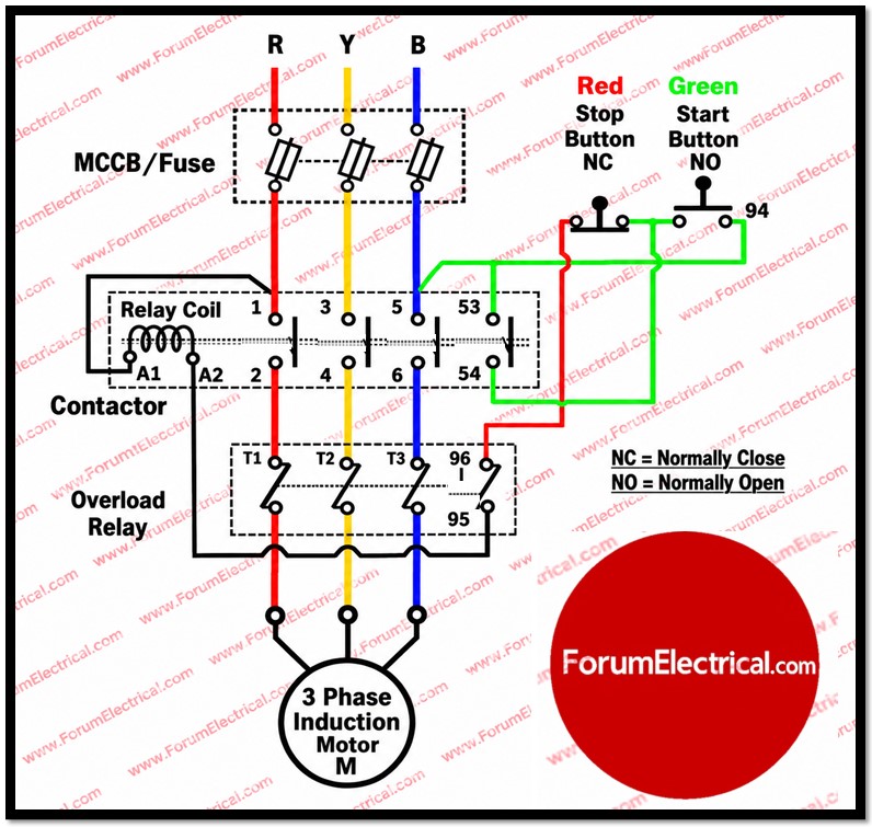
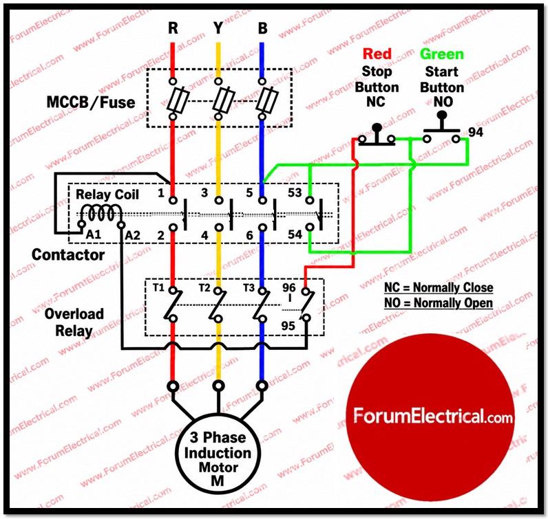
The power circuit is the path through which the actual three phase supply current flows to the motor windings.
It is rated to carry the full load current as well as the momentary starting surge current.
The power circuit of a DOL starter consists of the following components connected in series between the three-phase supply and the motor:
- Isolator / MCCB (Moulded Case Circuit Breaker) (or)) HRC Fuses provides manual isolation of the supply and protects the circuit against short circuit faults.
- Main Contactor (3-pole) is an electromagnetically operated switch that connects (or) disconnects all three supply lines to the motor simultaneously.
- Thermal Overload Relay (OLR) that is connected in series with the motor and it senses continuous overcurrent caused by overload conditions and trips the control circuit to protect the motor windings.
- Three-Phase Induction Motor is the load being started and protected.
Power circuit path: MCCB/Fuse → Main Contactor (3 poles) → Thermal Overload Relay → 3-Phase Induction Motor
Power Circuit Component Summary
| Component | Function |
| MCCB / HRC Fuse | Isolates the circuit manually and protects against short circuit and fault currents. |
| Main Contactor (3-Pole) | Switches all three phases to the motor on/off and operated by its energising coil. |
| Thermal Overload Relay | Monitors motor current continuously as it opens the control circuit on sustained overload to avoid winding damage. |
| 3-Phase Induction Motor | Converts electrical energy into mechanical rotational output. |
Control Circuit
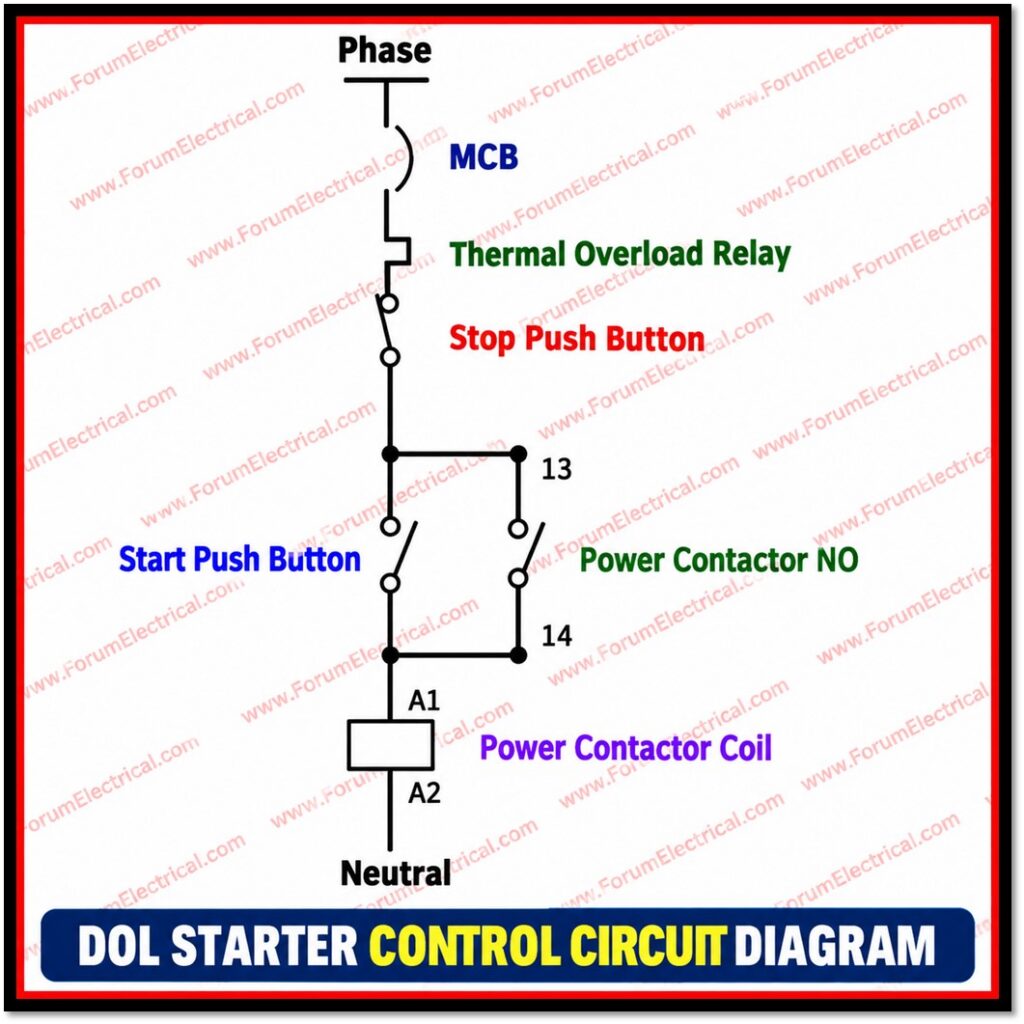
The control circuit operates at a lower current than the power circuit and is responsible for energizing and de-energizing the contactor coil which in turn switches the power circuit.
It typically operates from a single phase (line to neutral, or across two phases through a control transformer) and uses push buttons and auxiliary contacts rather than heavy power contacts.
The control circuit of a DOL starter includes:
- Start Push Button (Normally Open, NO) momentarily pressed to energise the contactor coil and start the motor.
- Stop Push Button (Normally Closed, NC) pressed to break the control circuit and de-energise the coil and stopping the motor.
- Contactor Coil is an electromagnet that when energised closes the main power contacts and the auxiliary contact.
- Auxiliary Holding (Seal-in) Contact is a normally open auxiliary contact wired in parallel with the Start button and it closes when the coil energises and ‘holds’ the circuit closed after the Start button is released.
- Overload Relay Contact (NC) wired in series in the control circuit and it opens automatically if the thermal overload relay trips, cutting power to the coil.
Control circuit path: Supply → Stop Button (NC) → Start Button (NO) [with Auxiliary Contact in parallel] → Overload Relay Contact (NC) → Contactor Coil → Neutral/Return
Control Circuit Component Summary
| Component | Function |
| Start Push Button (NO) | Initiates the starting sequence by completing the coil circuit momentarily. |
| Stop Push Button (NC) | Breaks the coil circuit to stop the motor; normally closed, opens when pressed. |
| Contactor Coil | Electromagnetic coil that closes the main and auxiliary contacts when energized. |
| Auxiliary Holding Contact | Maintains (seals in) the circuit after the Start button is released, enabling continuous run. |
| Overload Relay Contact (NC) | Opens the control circuit automatically during a sustained overload and protecting the motor. |
Step-by-Step Working Principle
- The MCCB/isolator is switched ON energizing the incoming supply up to the main contactor’s power contacts and the control circuit fuse.
- The operator presses the Start push button (NO) completing the control circuit and energising the contactor coil.
- The energised coil closes the three main power contacts, connecting full three-phase supply to the motor; simultaneously, the auxiliary contact (wired in parallel with the Start button) closes.
- The motor accelerates directly from standstill to full speed, drawing a high inrush current (typically six to eight times its rated current) for a brief period.
- Once the Start button is released, the closed auxiliary contact keeps the coil circuit alive and this is called the holding (or) seal-in function which allowing the motor to continue running.
- The motor runs continuously at rated speed under normal supply conditions with the thermal overload relay continuously monitoring the current drawn.
- To stop the motor, the operator presses the Stop push button (NC), which breaks the control circuit, de-energises the coil, opens the main contacts and disconnects the motor from supply.
- If the motor experiences a sustained overload, the thermal overload relay heats up and trips its NC contact in the control circuit, automatically de-energising the coil and stopping the motor and protecting it from thermal damage even without operator intervention.
Advantages of DOL Starter
- Simple and economical design that is very few components are required.
- Easy installation, wiring, and maintenance compared to reduced-voltage starters.
- Provides high starting torque, since the motor receives full rated voltage from the outset.
- Delivers full voltage supply directly to the motor terminals with no intermediate stages.
- Reliable and robust operation, particularly well suited to small and medium-sized motors.
- Fast acceleration to full speed, minimising the time spent in the high-slip starting condition.
Disadvantages of DOL Starter
- High starting (inrush) current, typically six to eight times the rated full-load current.
- Causes a voltage dip in the supply line during starting, which can affect other connected loads.
- Sudden full-torque application imposes mechanical stress on the motor shaft, coupling, and driven load.
- Not suitable for large-capacity motors, where the high inrush current can overload the supply network or violate utility restrictions.
- Can cause nuisance tripping of upstream protective devices if the supply system is weak.
Applications
DOL starters are commonly used for small industrial motors generally up to about 5 HP on single-phase systems and up to roughly 25 – 40 HP on three-phase systems depending on local utility regulations and the strength of the supply network where direct starting is both technically acceptable and the most cost-effective solution.
Typical applications include small pumps, fans, blowers, compressors, conveyors, grinders and general workshop machinery where the connected load does not require torque or current limiting during start-up.
Conclusion
The DOL starter remains one of the most fundamental and widely taught starting methods in industrial electrical engineering because it clearly illustrates the interaction between a power circuit and a control circuit.
The power circuit that comprising the MCCB/fuse, main contactor, overload relay, and motor which carries the actual current that drives the motor while the control circuit comprising the start and stop push buttons, the contactor coil and the auxiliary holding contact governs when that current flows.
While its high starting current and mechanical stress make it unsuitable for large motors, its simplicity, reliability and low cost ensure that the DOL starter continues to be the preferred choice for starting small and medium-sized three-phase induction motors across industrial and commercial installations.

