Power transformers are among the most critical and expensive assets in any electrical power network, and protecting them from thermal damage is essential to ensuring long service life and uninterrupted supply.
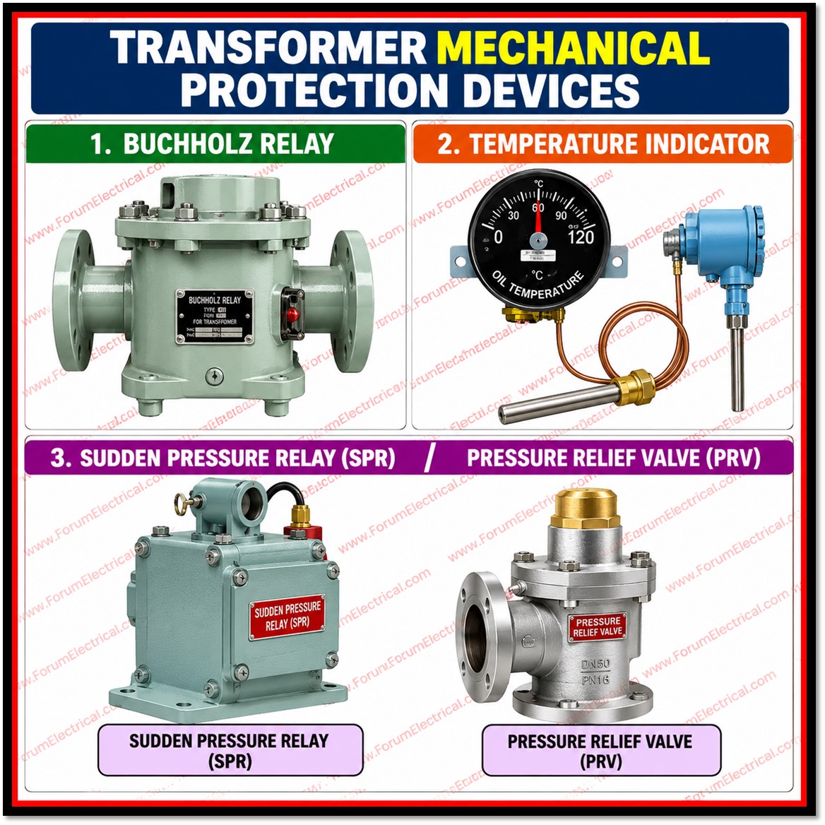
Alongside electrical protection schemes such as differential and Buchholz relays, transformers are fitted with a category of mechanical protection devices that continuously monitor physical operating conditions.
Two of the most fundamental instruments in this category are the
1). Winding Temperature Indicator (WTI) and
2). Oil Temperature Indicator (OTI).
The transformer’s cooling control & alarm/trip logic depend on both dial-type (or) digital controls on outside tank or marshalling/control cabinet.
This post describes the operation of each instrument, the criteria used to define their temperature thresholds, the mathematical concepts that control their readings and the field calibration procedure.
Winding Temperature Indicator (WTI)
The Winding Temperature Indicator monitors and displays the internal winding temperature of the power transformer.
Its primary purpose is to prevent insulation degradation that would otherwise be caused by sustained thermal overload of the windings, since insulation life is highly sensitive to operating temperature.
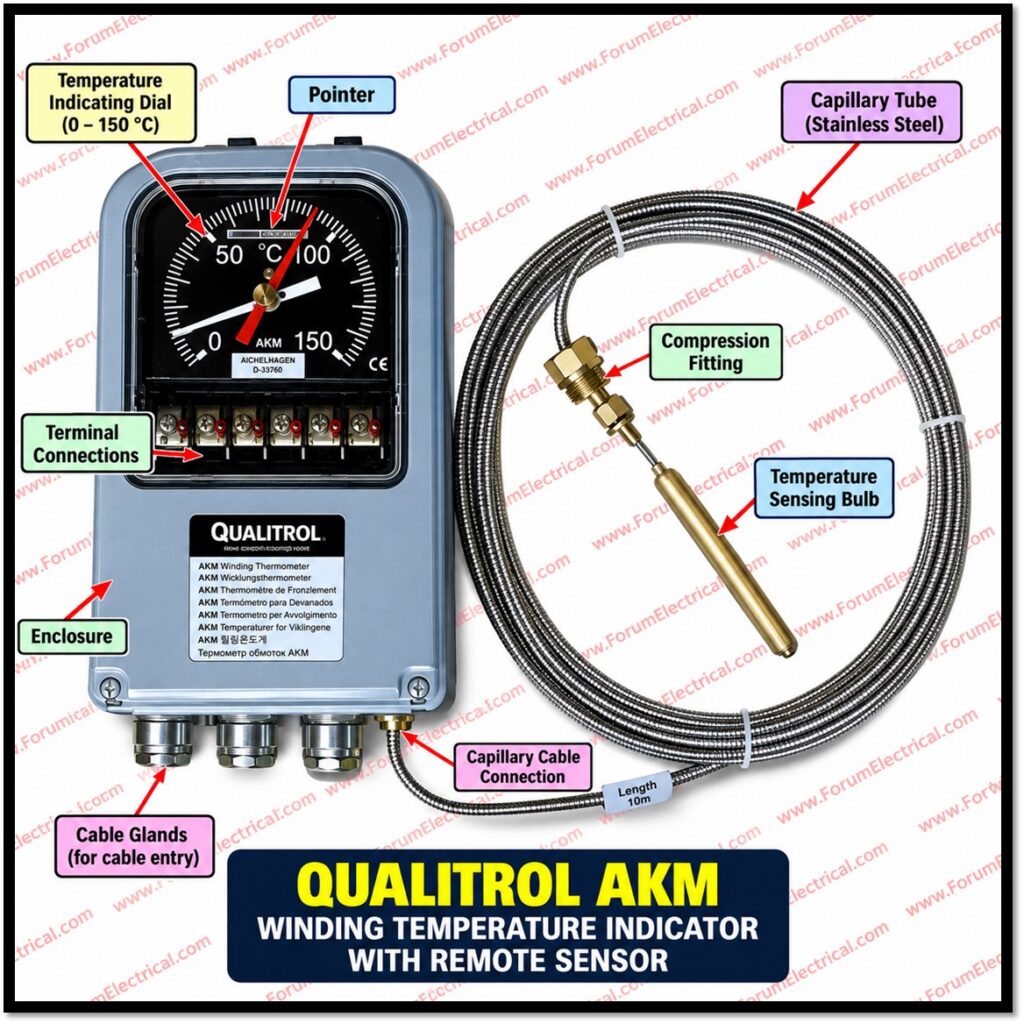
The WTI provides the earliest and most direct indication of winding heating and is therefore used to control the automatic cooling equipment and in extreme conditions, to initiate an alarm or a trip signal to isolate the transformer before insulation damage occurs.
Oil Temperature Indicator (OTI)
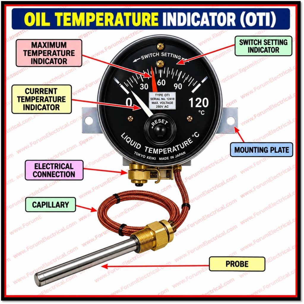
The Oil Temperature Indicator measures and displays the top-layer oil temperature inside the main transformer tank.
Because the top oil layer is the hottest part of the bulk insulating oil, its temperature is a reliable indicator of the transformer’s overall thermal condition.
The OTI reading is used both as an operational reference for the maintenance staff and as an input to the cooling control and protection scheme, working alongside the WTI to provide a complete thermal picture of the transformer.
Both the WTI and the OTI are fundamental mechanical protection devices, physically mounted on the outer shell or the control cabinet of the transformer and both use a similar dial mechanism with adjustable microswitch contacts that are wired into the cooling and protection circuits.
Temperature Setting Criteria
The temperature thresholds required to initiate Cooling Stage One, Cooling Stage Two, the Alarm warning, and the Circuit Breaker Trip are not fixed universally – they are dynamically determined according to the environmental conditions under which the transformer operates.
| Installation Type | Setting Consideration |
| Indoor Installation | Thresholds account for restricted airflow, elevated room ambient temperature, and reduced heat dissipation rates inside enclosed substations. |
| Outdoor Installation | Settings compensate for direct solar radiation on the tank surface and extreme seasonal ambient temperature fluctuations. |
Core Principles
Top Oil Temperature Calculation
The top oil temperature measured by the OTI is equal to the ambient air temperature plus the temperature rise caused by the internal losses of the transformer under load.
In other words, the reading combines a variable environmental component (ambient temperature) with a variable operational component (the load-dependent temperature rise), so the same absolute oil temperature can correspond to different combinations of ambient conditions and loading.
Winding Temperature Simulation Principle
The Winding Temperature Indicator does not make direct contact with the energised high-voltage windings, since this would be impractical and unsafe.
Instead, it simulates the winding temperature by measuring the top oil temperature and adding an additional thermal gradient that is generated artificially by a small heating element built into the WTI mechanism.
This heating element is fed from an internal current transformer that senses the load current, and the thermal gradient it produces is directly proportional to the square of that measured load current. This arrangement known as the ‘thermal image’ or ‘hot-spot simulation’ principle allows the WTI dial to track the winding hot-spot temperature closely even though no sensor is actually embedded inside the winding insulation.
Step-by-Step Calibration Procedure
Calibration of the WTI and OTI setpoints is a precise mechanical procedure carried out on the microswitch setting discs inside the indicator housing.
The following sequence is followed for each contact stage:
Step-1: Loosen the locking mechanism by carefully unfastening the primary adjustment screw on the internal microswitch setting disk.
Step-2: Set the Operational Target: Carefully align the calibrated dial till the target value (e.g., 60, 70, or 85 degrees Celsius) equals the fixed reference mark.
Step-3: Tighten the adjustment screw securely to prevent mechanical vibration throughout service from shifting the microswitch position.
Step-4: Secure the red maximum-peak drag indicator pointer over the specified setpoint.
Step-5: Calibrate Sequential Contacts: Make physical adjustments for each successive stage including the First Fan Group, Second Fan Group, Signal Alarm and Primary Trip contacts.
Typical Contact Stages and Their Purpose
| Stage | Typical Function |
| First Fan Group (Cooling Stage One) | When the temperature reaches a moderate level, the initial bank of cooling fans/pumps is activated. |
| Second Fan Group (Cooling Stage Two) | If the temperature rises over Stage One, the system activates extra cooling capability. |
| Signal Alarm Contact | An audio or visual alarm is triggered in the control room to alert operators of an aberrant temperature state. |
| Primary Trip Contact | If the temperature rises to a high, insulation-damaging level, the circuit breaker trips, isolating the transformer. |
Importance of Correct Calibration
- Ensures all the cooling equipment activates at the correct load and temperature conditions, avoiding both premature cycling and delayed response.
- Prevents nuisance alarms or trips caused by incorrectly set thresholds.
- Protects transformer insulation life, since insulation ageing accelerates sharply above rated hot-spot temperature.
- Provides a reliable maximum-temperature history through the drag pointer, useful for maintenance and fault investigation.
- Maintains coordination between the WTI, OTI, and the transformer’s overall protection and cooling control philosophy.
Conclusion
A transformers mechanical thermal protection system depends on the Winding and Oil Temperature Indicators.
The OTI measures top oil temperature directly whereas the WTI uses a thermal-image approach to approximate winding hot-spot temperature using oil temperature and a load-current-driven heating element.
Cooling stage, alert, and trip temperature thresholds must be adjusted for each installation because ambient conditions vary greatly between indoor & outdoor installations.
From the first fan group to the primary trip contact, each micro switch step is carefully calibrated to guarantee that the cooling system responds suitably to load and thermal conditions protecting the transformers insulation & extending its lifespan.

