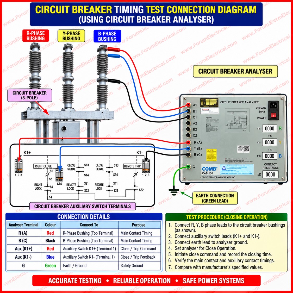
When commissioning and maintaining high voltage circuit breakers, engineers undertake a Contact Resistance Measurement (CRM) test to evaluate the primary contacts physical condition.
CRM testing can detect contact degradation, pitting, and inadequate contact pressure.
In high voltage power systems, time is as essential as contact health. If its poles do not open (or) close within manufacturer tolerances, a breaker with excellent contact resistance can be hazardous to run.
This post discusses why circuit breaker timing is important, what a timing test is, the primary field timing tests and how this analysis affects substation reliability.
Why Timing of a Circuit Breaker is Important?
A 3-phase circuit breaker is mechanically configured so that all 3 poles open and close nearly simultaneously. This synchronization is not an ease of use; rather, it is a fundamental design necessity based on the physical characteristics of a 3 phase fault interruption & the mechanical tolerances of the breaker operating mechanism, either spring, hydraulic or pneumatic.
When one pole runs earlier or later than the other 2, even by a slight margin, the effects can be felt throughout the electrical system.
IEC 62271-100 addresses high voltage alternating current (AC) circuit breaker testing, whereas IEC 60947-2 addresses low-voltage breakers.
The following issues are typically linked to inadequate pole synchronization:
Unbalanced Current Interruption
Unbalanced current interruption occurs when one pole clears a fault current before the others, causing the other poles to interrupt an asymmetrical (or) greater magnitude of current than their design capacity.
Overvoltage stress on Insulation
Timing mismatches can cause transient overvoltages through bushings, transformers, and switchgear insulation, leading to accelerated aging and flashover under stress.
Mechanical stress on Equipment
Uneven operation causes asymmetrical torque and vibration on the breaker’s linkage, drive shaft, and support structure, leading to premature wear or failure.
Protection Miscoordination
Certain protection schemes including as breaker failure prevention, autoreclosing and current differential protection, rely on near-simultaneous pole operation.
Timing deviations might result in false operations or delay fault clearance.
Even a few milliseconds of gap between poles can cause anomalous system conditions, especially on transmission-class breakers with high fault currents and system voltages.
Timing tests are so required as part of either commissioning or preventative maintenance procedures.
What is a Circuit Breaker Timing Test?
Circuit breaker timing tests evaluate the exact operating time of the breaker contacts from trip or close to contact opening or closing.
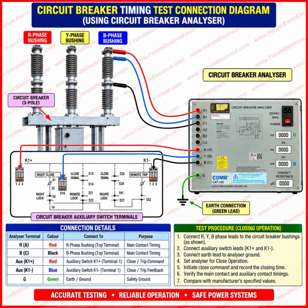
To do this, connect a timing analyzer to the breaker control circuit and its (52a/52b) auxiliary contacts which mirror its primary contacts.
The timing analyzer applies the protection relay (or) control switch trip (or) close signal and records each poles contact change with millisecond accuracy.
IEEE C37.09 specifies standard test procedures for the high-voltage AC circuit breakers together with rating and application guidelines in IEEE C37.04 and C37.06.
The collected data enables engineers compare measured operating intervals to the breaker manufacturers technical datasheet (or) type test report & to check the spread between poles.
Main Tests Performed in Breaker Timing Analysis
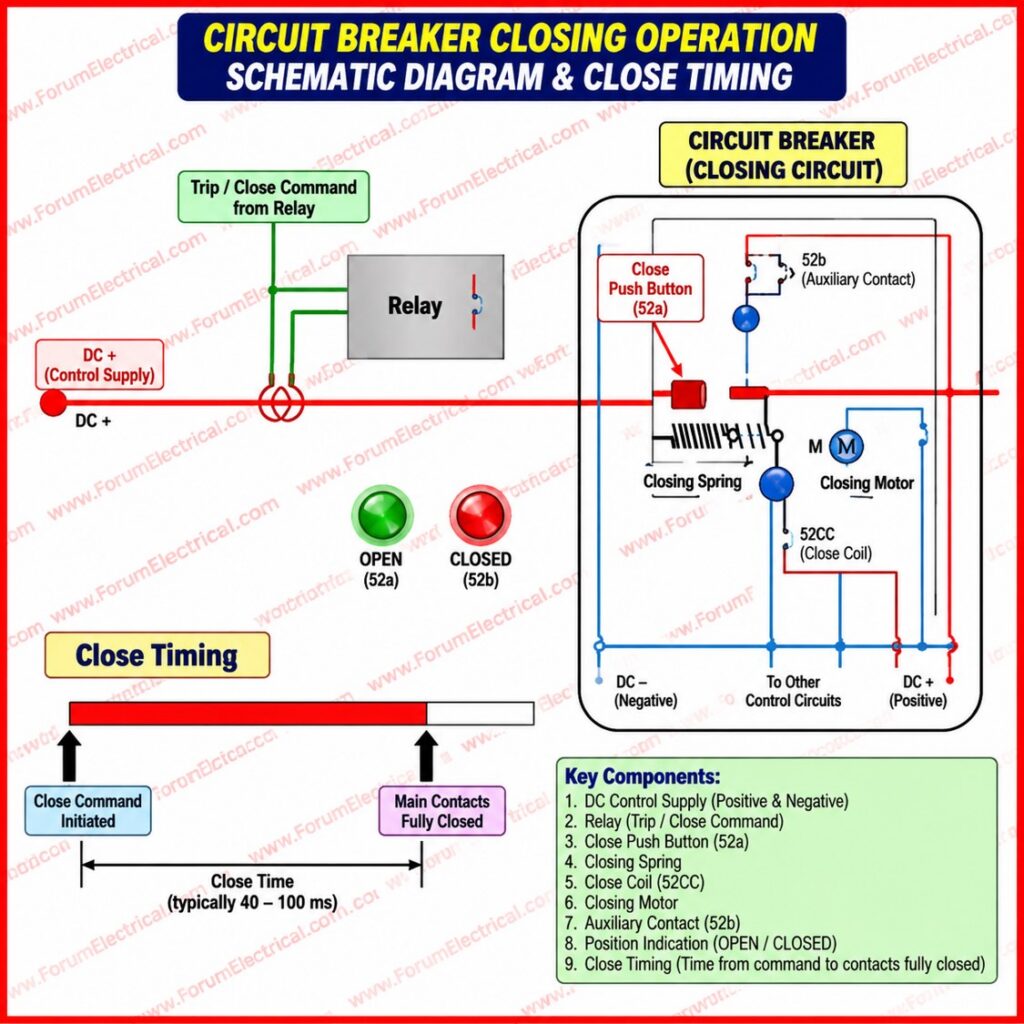
Close Operation Test
In the close operation test, a close command is issued to the breaker through the timing analyzer. The instrument measures:
- Closing time of each individual pole, measured from command initiation to contact touch.
- Pole-to-pole closing time difference, i.e., the spread between the fastest and slowest closing pole.
This test confirms that all three poles close nearly simultaneously, which is essential to avoid inrush current asymmetry and to ensure the breaker can be safely energized under all system conditions, including closing onto a fault (in conjunction with pre-insertion resistors or point-on-wave controllers where fitted).
Open (Trip) Operation Test
In the open, or trip, operation test, a trip command is applied to the breaker. The analyzer records:
- Opening time of each pole, measured from command initiation to contact parting.
- Pole-to-pole opening time difference across the three phases.
This test confirms that the breaker is capable of interrupting fault current correctly and simultaneously across all three phases during an actual fault condition which is the single most safety-critical function of the breaker.
IS 13118 & IS 13947 (Part 2) are closely related to international IEC equivalents for domestic based equipment.
Close–Open Operation Test (Auto-Reclose Simulation)
Many transmission-class breakers are equipped with single-shot or multi-shot auto-reclosing schemes to restore supply automatically after a transient fault. To validate this function, a close–open test is performed in which:
- A close command is issued and the breaker closes.
- The trip command is applied immediately after (when the breaker is still finishing its closing stroke or soon after closing).
- The timing analyzer records the complete operating sequence, including the close time, the minimum arcing or dead time between operations, and the subsequent open time of each pole.
This test verifies that the breaker’s mechanism, whether spring-charged, hydraulic, or pneumatic, can reliably perform the fast close-open sequence demanded by auto-reclosing schemes on transmission systems without mechanical hesitation, contact bounce, or excessive pole discrepancy.
Typical Acceptance Criteria
While exact values vary by manufacturer, voltage class, and mechanism type, the table below summarizes the general parameters engineers evaluate during a timing test.
| Parameter | Typical Range | Significance | Consequence if Exceeded |
|---|---|---|---|
| Closing time | 40–100 ms | Time from close command to contact touch | Delayed energization, inrush asymmetry |
| Opening time | 20–50 ms | Time from trip command to contact parting | Delayed fault clearance |
| Pole discrepancy (open/close) | ≤ 2–5 ms | Simultaneity between the three poles | Overvoltage, unbalanced interruption |
| Contact bounce time | As low as possible | Re-touch of contacts after closing | Arcing damage, contact erosion |
| Dead time (reclose) | Per scheme design | Interval between open and reclose | Reclose miscoordination, instability |
These values must always be verified against the specific breaker’s type-test certificate and the manufacturer’s maintenance manual, since permissible tolerances differ significantly between air-blast, SF6, vacuum, and oil circuit breakers, as well as between mechanism designs.
Practical Takeaway
A circuit breaker may appear perfectly healthy from the outside clean contacts, correct contact resistance readings, and no visible mechanical damage but incorrect operating timing between poles can still create serious system stress that is invisible to a simple contact resistance test. Timing deviations do not announce themselves under normal load conditions; they reveal themselves only during a fault, at the exact moment the power system needs the breaker to perform flawlessly.
This is why timing analysis, performed alongside contact resistance measurement, insulation resistance testing, and dynamic resistance measurement, forms a critical part of substation commissioning and preventive maintenance programs. Together, these tests ensure that a circuit breaker is not only mechanically intact but also operates with the precision, synchronism, and speed that a modern power system demands.
Summary
- CRM testing verifies contact health yet does not verify pole timing or synchronism.
- All three poles of a breaker must open and close almost simultaneously to avoid system stress.
- A timing analyzer connected to control and auxiliary contacts measures operating times to millisecond accuracy.
- The three principal tests are the Close Operation Test, the Open (Trip) Operation Test, and the Close–Open (auto-reclose simulation) Test.
- Even millisecond-level pole discrepancies can cause overvoltage stress, unbalanced interruption, mechanical wear, and protection miscoordination.
- Timing tests are mandatory during both the commissioning & periodic maintenance of high-voltage circuit breakers.

