Programmable Logic Controller (PLC)
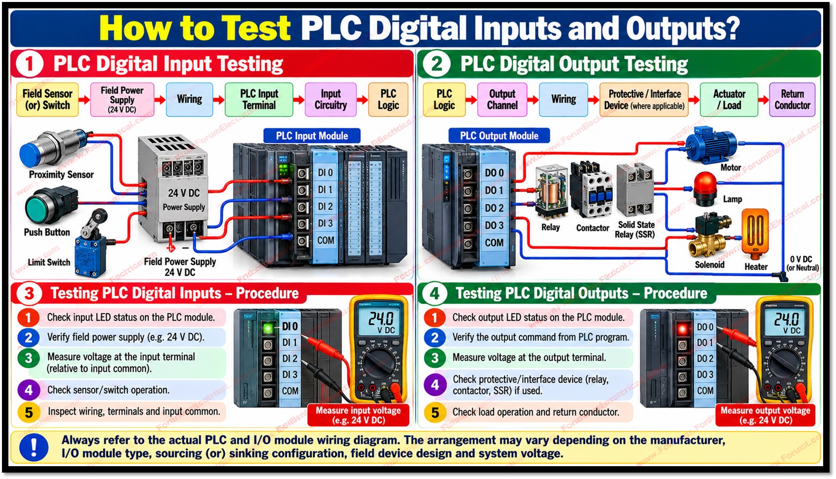
Programmable Logic Controller (PLC) digital inputs and outputs form the interface between a control system and field equipment.
- Programmable Logic Controller (PLC)
- Safety Precautions
- PLC I/O Signal Path
- Testing PLC Digital Inputs
- 1). Check the PLC Input LED
- 2). Verify the Field Device
- 3). Measure the PLC Input
- Testing PLC Digital Outputs
- 1). Check the Output LED
- 2). Check the Output Circuit
- 3). Check the Final Load
- Common PLC Digital I/O Faults
- Practical Troubleshooting
- Importance of Accurate Wiring
- Final PLC I/O Testing Checklist
- Conclusion
Digital inputs receive discrete ON/OFF signals from
- Selector switches,
- Proximity sensors,
- Photoelectric sensors,
- Limit switches and
- Other field devices.
Digital outputs send discrete control signals to
- Contactor coils,
- Solenoid valves,
- Pilot lamps,
- Interposing relays and
- Other actuators.
An I/O fault can stop a machine, disturb an automatic sequence (or) create an intermittent process problem.
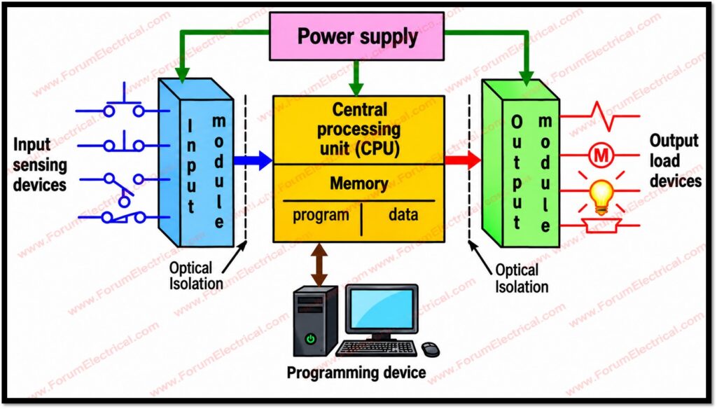
Effective troubleshooting should therefore follow the actual signal path instead of relying on random measurements.
Start with the machine sequence, PLC diagnostics and I/O indicators, then verify the field device, wiring, power supply, configuration and final load in a logical order.
Safety Precautions
PLC panels may contain 24 VDC control circuits as well as 120 VAC, 230 VAC, 400 VAC (or) higher voltage circuits.
Follow the site electrical safety procedure, applicable lockout/tagout requirements, risk assessment and equipment manufacturer instructions.
- Identify and isolate hazardous energy sources before opening panels (or) disconnecting conductors.
- Use a correctly rated and inspected multimeter and suitable test leads.
- Do not bypass safety circuits (or) machine interlocks simply to force operation.
- Use appropriate PPE and safe energized testing practices when live measurements are necessary.
- Never assume earth is the correct measurement reference. So, use the reference specified by the wiring diagram.
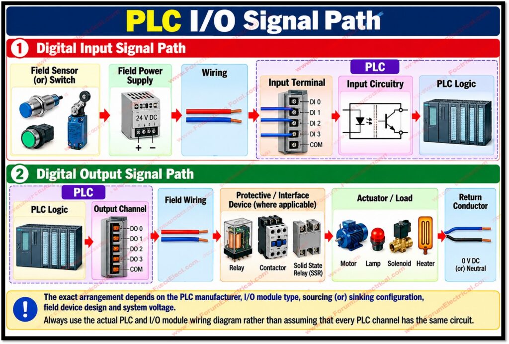
PLC I/O Signal Path
For a typical digital input, the signal path can be represented as:
Field sensor (or) switch → field power supply → wiring → PLC input terminal → input circuitry → PLC logic.
For a typical digital output, the signal path can be:
PLC logic → output channel → field wiring → protective or interface device where applicable → actuator/load → return conductor.
The exact arrangement depends on the PLC manufacturer, I/O module type, sourcing (or) sinking configuration, field device design and system voltage.
Always use the actual PLC and I/O module wiring diagram rather than assuming that every PLC channel has the same circuit.
Testing PLC Digital Inputs
1). Check the PLC Input LED
The input channel LED is one of the quickest diagnostic indicators.
Operate the field device & observe whether the corresponding PLC input LED changes the state.
If the field device changes state yet the PLC indication does not, continue tracing the signal instead of quickly replacing the module.
2). Verify the Field Device
Inspect the sensor (or) switch for mechanical damage, contamination, incorrect alignment, loose terminals and damaged cables.
For a proximity (or) photoelectric sensor, verify its supply voltage and confirm that its output changes state when the operating condition changes.
- Check sensor supply voltage at the sensor terminals.
- Confirm that the sensor output changes between it’s expected OFF & ON states.
- For mechanical contacts, check continuity only under safe and appropriate test conditions.
- Inspect connectors, junction boxes & terminal blocks for looseness, corrosion (or) damaged conductors.
3). Measure the PLC Input
Measure voltage at the PLC input terminal using the correct reference point shown on the wiring diagram.
For a typical 24 VDC input, an ON signal may be near the control supply voltage and an OFF signal may be near 0 V but the actual ON/OFF thresholds are module specific.
If the sensor output is correct at the sensor but the PLC input terminal does not receive the expected signal, analyze the
- Cable,
- Terminals,
- Junction boxes,
- Fuses and intermediate devices.
If the expected voltage reaches the input terminal but the input status remains incorrect, check the module specification, common/reference wiring, PLC configuration & channel condition.
Testing PLC Digital Outputs
1). Check the Output LED
Command the output through the PLC logic under safe test conditions and observe the corresponding output LED.
An output LED that turns ON indicates that the PLC is requesting the output state but it does not by itself prove that the load is receiving the correct voltage (or) operating correctly.
2). Check the Output Circuit
With the output commanded ON, measure the electrical condition at the appropriate output terminals and load circuit using the wiring diagram as the reference.
The test method depends on whether the output is relay, transistor, triac (or) another type.
- Verify the output supply and common/return connections.
- Check output fuses and protective devices where installed.
- Inspect terminals, connectors and field cables.
- Check interposing relays, contactors (or) solid state interfaces where used.
- Verify that the load voltage and current are within the interface and device ratings.
3). Check the Final Load
If the output LED is ON and the expected electrical condition is present at the load terminals but the device does not operate, check the load itself.
- For a solenoid, verify the coil condition & manufacturer requirements.
- For a contactor, inspect the coil, auxiliary contacts and mechanical movement.
- For a lamp, check the lamp (or) driver and its return path.
A useful troubleshooting principle is to measure across the component being tested.
A voltage measurement referenced to an inappropriate point can be misleading.
A floating (or) disconnected return conductor, for example, can generate unexpected voltage readings even though the load cannot operate.
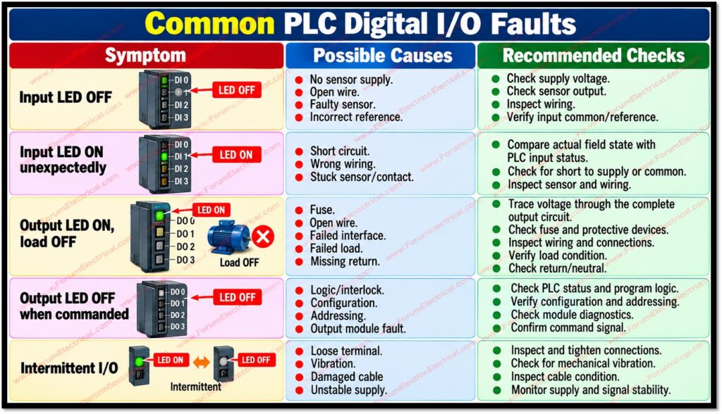
Common PLC Digital I/O Faults
| Symptom | Possible Causes | Recommended Checks |
| Input LED OFF | No sensor supply, open wire, faulty sensor, incorrect reference. | Check supply, sensor output, wiring and input common. |
| Input LED ON unexpectedly | Short circuit, wrong wiring, stuck sensor/contact. | Compare actual field state with PLC input status. |
| Output LED ON, load OFF | Fuse, open wire, failed interface, failed load, missing return. | Trace voltage through the complete output circuit. |
| Output LED OFF when commanded | Logic/interlock, configuration, addressing, output fault. | Check PLC status, program logic, configuration and module diagnostics. |
| Intermittent I/O | Loose terminal, vibration, damaged cable, unstable supply. | Inspect connections and monitor supply/signal stability. |
Practical Troubleshooting
Use a structured sequence to avoid unnecessary replacement of sensors, wiring (or) PLC modules:
- Identify the affected machine function and PLC I/O address.
- Check PLC diagnostics and the relevant input/output LED.
- Verify the field device power supply and operating condition.
- Trace the signal through terminals, cables & intermediate devices.
- Measure the expected electrical voltage (or) continuity at the exact reference points.
- Compare the accurate measurement with the PLC/module & device specifications.
- Check PLC logic, interlocks, permissives & I/O (Input/Output) configuration.
- Test the output electrical circuit & final load where applicable.
- Correct the electrical fault & perform a controlled functional test.
- Update the wiring diagram, all the maintenance record & fault history.
Importance of Accurate Wiring
Up-to-date wiring diagrams significantly reduce troubleshooting time.
Drawings should identify
- PLC rack and module numbers,
- I/O addresses,
- Terminal numbers,
- Wire numbers,
- Power supplies,
- Commons,
- Fuses,
- Interposing relays and
- Final loads.
Any approved modification should be reflected in the controlled drawing set.
Good documentation helps technicians distinguish a field device fault from a wiring fault (or) I/O-module problem.
When the expected signal path and reference points are known every measurement has a clear purpose.
Final PLC I/O Testing Checklist
- PLC diagnostics checked.
- Input/output LED status verified.
- Field-device supply verified.
- Correct meter reference point confirmed.
- Wiring and terminals inspected.
- Fuses and intermediate interfaces checked.
- Expected signal compared with measured signal.
- PLC logic, interlocks and configuration checked.
- Final load operation verified.
- Fault and corrective action documented.
Conclusion
Testing PLC digital inputs and outputs is most effective when performed systematically from the field device toward the PLC and from the PLC toward the final load.
LED indicators provide an important first diagnostic clue but they should be combined with wiring diagram review, PLC diagnostics & correctly planned electrical measurements.
Avoid random probing & predict the expected measurement before testing.
This makes it easier to determine whether the problem is in the field device, power supply, wiring, interface equipment, PLC configuration (or) I/O module.
Accurate drawings, correct testing and proper documentation make PLC troubleshooting faster, safer and more reliable.

