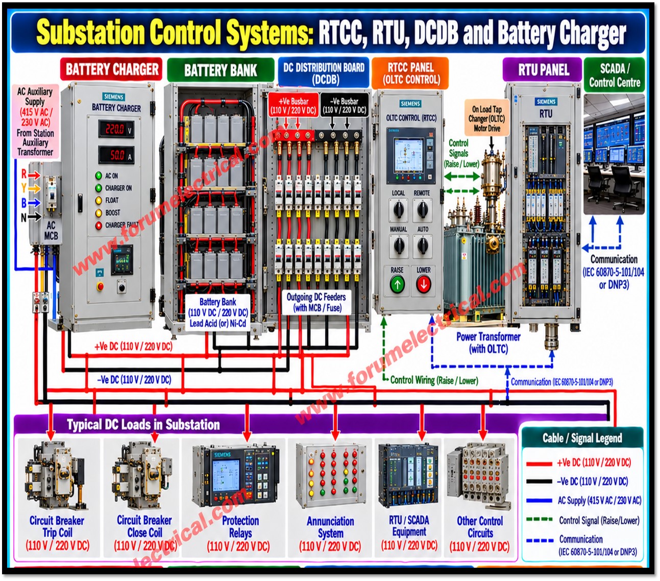
A modern substation depends on several auxiliary systems that work together with primary equipment such as
- Transformers and
- Circuit breakers.
This post describes four of them:
- Remote Tap Changer Control (RTCC) panel,
- Remote Terminal Unit (RTU) panel,
- DC Distribution Board (DCDB) and
- Battery Charger.
The RTCC regulates voltage, the RTU provides the communication link to the Control Center and the Battery Charger and DCDB supply the reliable DC power on which control, protection and communication depend.
RTCC Panel – Remote Tap Changer Control
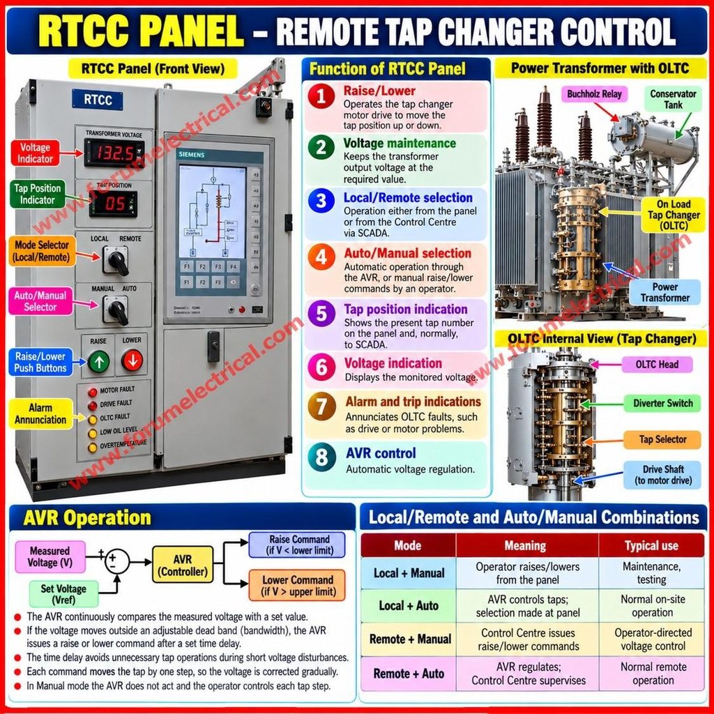
The RTCC panel is used to control the On Load Tap Changer (OLTC) of a power transformer.
The OLTC changes the number of effective turns in a transformer winding while the transformer remains energized and loaded which changes the voltage ratio and therefore the output voltage.
Main Functions
- Raise/Lower: operates the tap changer motor drive to move the tap position up or down.
- Voltage maintenance: keeps the transformer output voltage at the required value.
- Local/Remote selection: operation either from the panel or from the Control Centre via SCADA.
- Auto/Manual selection: automatic operation through the AVR, or manual raise/lower commands by an operator.
- Tap position indication: shows the present tap number on the panel and, normally, to SCADA.
- Voltage indication: displays the monitored voltage.
- Alarm and trip indications: annunciates OLTC faults, such as drive or motor problems.
- AVR control: automatic voltage regulation.
AVR Operation
The Automatic Voltage Regulator continuously compares the measured voltage with a set value.
If the voltage moves outside an adjustable dead band (bandwidth), the AVR issues a raise (or) lower command after a set time delay which avoids unnecessary tap operations during short voltage disturbances.
Because each command moves the tap by one step, the voltage is corrected gradually.
In Manual mode the AVR does not act and the operator controls each tap step.
Local/Remote and Auto/Manual Combinations
| Mode | Meaning | Typical use |
|---|---|---|
| Local + Manual | Operator raises/lowers from the panel | Maintenance, testing |
| Local + Auto | AVR controls taps; selection made at panel | Normal on-site operation |
| Remote + Manual | Control Centre issues raise/lower commands | Operator-directed voltage control |
| Remote + Auto | AVR regulates; Control Centre supervises | Normal remote operation |
RTU Panel: Remote Terminal Unit
The RTU collects information from different substation equipment and sends it to the SCADA/Control Center.
It also receives remote commands from the Control Center and passes them to the equipment.
Data Collected
| Type | Examples |
|---|---|
| Digital status | Circuit Breaker ON/OFF, isolator status, transformer alarms, protection relay signals |
| Analogue values | Voltage, current, MW, MVAR, frequency |
| Remote commands | Breaker open/close and, where configured, tap raise/lower commands |
Status and alarms are acquired as digital inputs, measurements are normally acquired as analogue values (directly or through transducers or communication with meters) and control commands are issued through digital outputs.
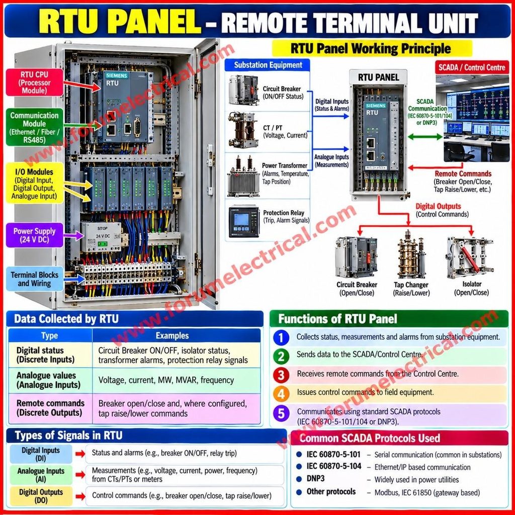
The RTU communicates with the Control Centre using a standard SCADA protocol, commonly IEC 60870-5-101/104 (or) DNP3.
DC Distribution Board (DCDB)
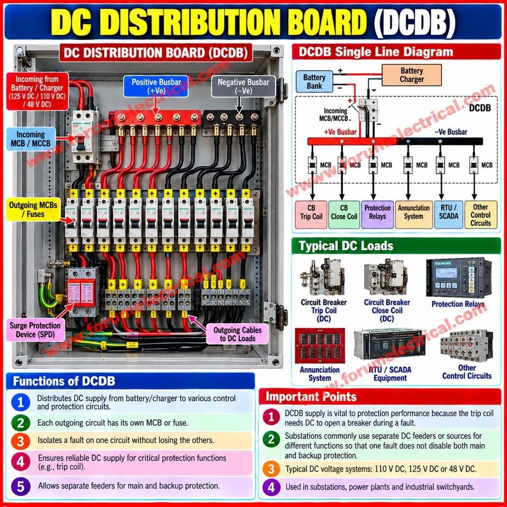
The DCDB distributes the DC supply from the battery/charger system to the various control and protection circuits.
Each outgoing circuit normally has its own MCB (or) fuse so a fault on one circuit is isolated without losing the others.
Typical DC Loads
- Circuit Breaker Trip Coil and Close Coil
- Protection relays
- Annunciation system
- RTU/SCADA equipment
- Other control circuits
Since the trip coil needs DC to open a breaker during a fault, the DCDB supply is vital to protection performance.
Substations commonly use separate DC feeders or sources for different functions so that one fault does not disable both main and backup protection.
Battery Charger
The Battery Charger keeps the battery bank charged and supplies the DC system.
During normal operation, it converts the AC auxiliary supply to DC, feeds the DC loads and maintains the battery.
When the AC supply fails, the battery bank supplies the DC loads without interruption.
Charger Functions
| Function | Purpose |
|---|---|
| Float charging | Maintains the battery at full charge at a constant voltage during normal operation |
| Boost/Equalizing charging | Higher-voltage charging to recharge quickly after a discharge (or) to equalize cells |
| DC voltage/current indication | Shows output voltage and current |
| AC fail alarm | Indicates loss of the AC input supply |
| Charger fail alarm | Indicates a fault in the charger |
| DC high/low voltage alarm | Warns of abnormal DC bus voltage |
Typical Arrangement: AC Supply → Battery Charger → DCDB → Control & Protection.
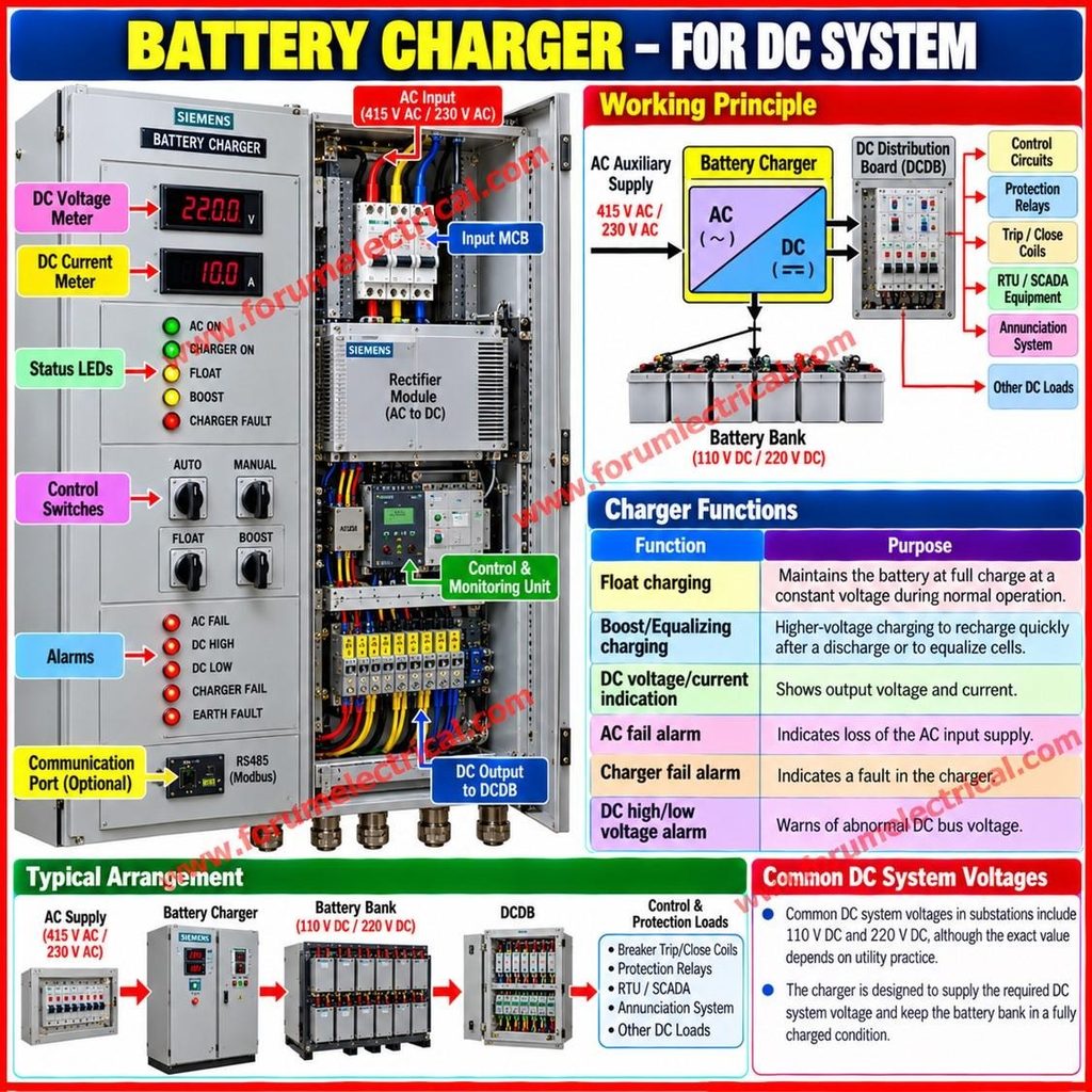
Common DC system voltages in substations include 110 V and 220 V although the exact value depends on utility practice.
Overall Function
AC Supply
↓
Battery Charger
↓
Battery Bank / DC System
↓
DCDB
↓
CB + Protection Relay + Control + RTU
In addition, the Transformer OLTC is controlled by the RTCC Panel (Transformer OLTC ↔ RTCC Panel), and the RTU communicates with the SCADA/Control Center (RTU → SCADA / Control Centre).
These chains are connected.
The charger and battery power the DCDB; the DCDB powers the breaker coils, relays, control circuits and RTU; the RTU reports to SCADA and the Control Center can send commands back through it.
A DC failure can therefore affect protection, control and remote monitoring at once which is why charger and battery alarms deserve priority.
| Equipment | Function | Key Features |
|---|---|---|
| RTCC Panel | Controls OLTC | Maintains required voltage via AVR; Local/Remote, Auto/Manual |
| RTU Panel | Data and command link | Sends status/measurements to SCADA; receives commands |
| DCDB | DC distribution | Separate MCBs/fuses for each control and protection circuit |
| Battery Charger | DC source and battery maintenance | Float/boost charging and alarms; battery gives backup |
Together, these systems regulate voltage, keep operators informed & ensure the substation can operate and protect itself even when the AC auxiliary supply is lost.

