
AC-to-DC conversion is a fundamental process in power electronics.
Many electronic devices including
- Control circuits,
- Sensors,
- Communication equipment,
- Computers, and
- Embedded systems
that require direct current (DC) while the available source may be alternating current (AC).
The source may be utility mains (or) the secondary winding of an AC transformer.
An AC-to-DC power supply converts this alternating input into a DC output suitable for the load.
A basic supply commonly contains three functional stages:
- Rectification,
- Smoothing and
- Regulation.
These stages have different purposes.
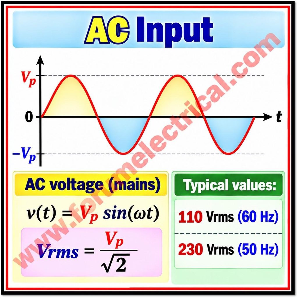
Rectification changes the direction of current through the load so that the output is unidirectional and smoothing reduces the resulting voltage variation known as ripple and regulation helps maintain the required output voltage despite changes in input voltage (or) load current.
A practical design may also include a transformer, input protection, filtering, thermal management and electrical-safety measures.
Rectification: Converting AC into Pulsating DC
A rectifier uses semiconductor diodes to conduct current preferentially in one direction.
The output is called pulsating DC because its polarity remains the same across the load but its instantaneous magnitude changes with time.
The 2 common basic arrangements are
- Half-wave rectifiers and
- Full-wave rectifiers.
1). Half-Wave Rectifier
A half-wave rectifier typically uses one diode in series with a resistive load.
During the half-cycle that forward-biases the diode and current flows through the load.
During the opposite half-cycle, the diode is reverse-biased and ideally blocks current.
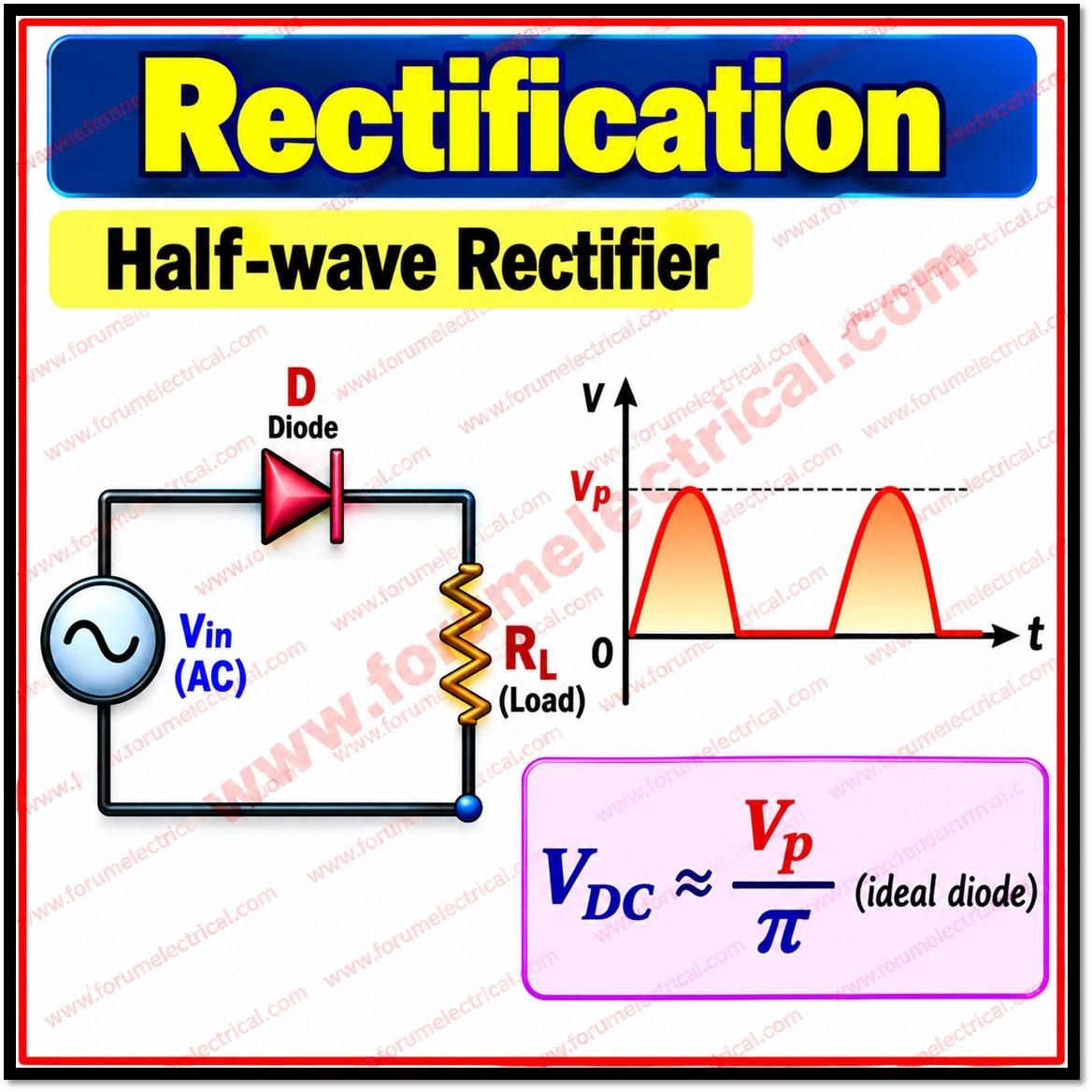
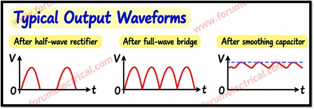
The output therefore contains pulses for only one half of each input cycle.
For an ideal diode and a sinusoidal input with peak voltage Vp, the average output across a resistive load is Vp/π.
The ripple frequency is equal to the AC supply frequency.
Half-wave rectification is simple and inexpensive but it has relatively high ripple & makes less effective use of the input waveform.
2). Full-Wave Bridge Rectifier
A full-wave bridge rectifier generally uses 4 diodes.
During each half-cycle, a pair of diodes conducts while the other pair blocks.
The conducting pair routes current through the load in the same direction for both halves of the AC waveform.
The output pulses occur twice per input cycle, so the ripple frequency is 2f, where f is the AC input frequency.
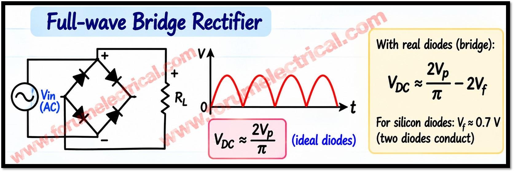
For an ideal sinusoidal source and resistive load, the average full-wave output is 2Vp/π.
Compared with half-wave rectification, a bridge rectifier normally provides a higher average output and lower ripple for the same input peak and load before filtering.
In a real bridge rectifier, current passes through two forward-biased diodes in series during each conducting path.
The approximate peak available after the bridge is therefore
Vp − 2VF
Where
VF – forward voltage of one conducting diode.
For silicon diodes, a rough estimate is about 0.7 V per diode at a relevant operating current, giving about 1.4 V total.
This is an approximation, not a fixed value: forward voltage depends on diode type, current, temperature and datasheet conditions.
The transformer secondary voltage is usually specified as an RMS value, so for a sinusoid its peak is approximately
Vrms X √2
before accounting for transformer regulation, source impedance and diode drops.
Smoothing: Reducing Ripple
Rectifier output is not perfectly steady DC.
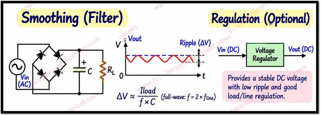
A smoothing capacitor connected across the load stores energy when the rectified voltage rises and supplies current to the load as the rectified voltage falls.
In a capacitor-input supply, the capacitor charges near the peaks of the rectified waveform, approximately to the peak voltage minus the conducting diode drops.
Between peaks, the diodes stop conducting when the source voltage falls below the capacitor voltage and the capacitor discharges through the load.
This action reduces the variation in output voltage.
The remaining variation is called ripple.
For a simple capacitor-input filter, a commonly used approximate relation for peak-to-peak ripple is
ΔV ≈ Iload/(fripple C)
Where
Iload – approximate DC load current
C – Capacitance and
fripple – Ripple frequency.
Thus, for the same load current and capacitance, full-wave rectification generally generates about half the ripple of half-wave rectification because its ripple frequency is twice as high.
This approximation assumes reasonably small ripple and a nearly constant load current and exact results depend on the circuit, source impedance, conduction angle, capacitor characteristics and load.
Increasing capacitance usually reduces ripple but a larger capacitor also increases charging-current pulses and diode/transformer peak current.
The capacitor must have an adequate voltage rating, ripple-current rating, temperature rating and expected service life.
Its polarity must be correct if an electrolytic capacitor is used.
A bleeder (or) discharge resistor may be appropriate so that stored charge does not remain hazardous after power is removed.
Capacitor selection should be based on both ripple requirements & component ratings rather than capacitance alone.
Voltage Regulation: Maintaining a Stable Output
Smoothing reduces ripple but does not, by itself, guarantee a constant DC voltage.
The output may still change with AC input variation, load current, transformer regulation, diode drops & capacitor discharge.
A voltage regulator is used when the load requires a more stable supply.
A linear regulator controls its pass element to maintain a specified output voltage that provided the input remains sufficiently above the output and the device stays within its current and thermal limits.
The difference between input and output voltage is dissipated mainly as heat approximately
P ≈ (Vin − Vout) x Iout
A heat sink may be required.
The minimum input-to-output voltage difference needed for proper operation is called dropout voltage and the exact value depends on the regulator.
A switching regulator uses controlled switching and energy-storage components to convert voltage more efficiently in many applications, although it can introduce switching noise and requires appropriate filtering and layout.
A regulators ability to reject changes in input voltage is described by line regulation while its response to changes in load current is described by load regulation.
- Ripple rejection,
- Output-current capability,
- Transient response,
- Protection features and
- Thermal performance
are also important selection criteria.
A regulator cannot correct every design problem: its input should remain within its specified operating range and the unregulated supply must provide enough voltage under the worst expected load & mains conditions.
Solved Example: Estimating the DC Level
Suppose a transformer provides 12 V RMS AC to a silicon bridge rectifier. The sinusoidal peak is approximately 12 x √2 = 16.97 V.
Using a simplified 0.7 V forward drop for each of the two conducting diodes, the peak at the bridge output is approximately 16.97 − 1.4 = 15.57 V.
A reservoir capacitor may charge close to this value at light load but the actual DC voltage will be lower under load because of ripple, transformer winding resistance, diode behavior & other losses.
This estimate is not a promise of a regulated 15.57 V output.
The capacitor voltage falls between charging peaks, and a regulator needs sufficient headroom above its target output.
For example, a conventional linear regulator set to 12 V may not regulate correctly if the capacitor’s trough falls below the regulator’s required input voltage.
The designer should calculate (or) measure the minimum input voltage at maximum load and low-line input, then check the regulator datasheet.
The example also assumes the 12 V RMS value is the actual loaded secondary voltage; transformer regulation can make the no-load voltage appreciably higher.
Design Checks, Safety and Common Mistakes
Choose rectifier diodes for adequate reverse-voltage rating, average and surge current capability, and thermal performance.
A bridge’s reverse-voltage requirements depend on the circuit and input conditions; select parts using the manufacturer’s application guidance.
Check transformer VA rating, winding current, fuse protection, inrush current, wiring, PCB spacing and enclosure requirements.
The capacitor’s maximum voltage must exceed the highest credible voltage, including high mains and no-load transformer conditions with suitable design margin.
Do not assume that a capacitor makes an output perfectly smooth, or that a regulator can operate with any input voltage.
Do not subtract only one diode drop when estimating the conducting path of a conventional bridge: 2 diodes normally conduct in series.
Also distinguish RMS input voltage from peak voltage.
For a sine wave, peak voltage is √2 times RMS voltage, but the relation differs for non-sinusoidal waveforms.
Ripple frequency is f for half-wave rectification and 2f for full-wave rectification.
These relationships are useful first estimates, but final design should be verified using component datasheets and measurements under minimum and maximum line, load and temperature conditions.
Mains-powered circuits can cause fatal electric shock and fire.
Use appropriate isolation, fusing, earthing, insulation, enclosure protection, and safe working procedures.
A transformer does not make every circuit safe and a charged capacitor can retain dangerous energy after disconnection.
Work on primary-connected equipment should be performed only by suitably trained personnel with suitable test equipment and procedures.
Conclusion
Rectification uses diodes to produce unidirectional, pulsating voltage.
Smoothing uses energy storage commonly a capacitor to reduce ripple.
Regulation controls the output to improve voltage stability when input (or) load conditions vary.
Good results depend on understanding
- RMS and peak voltage,
- Diode forward drops,
- Ripple frequency,
- Load current,
- Capacitor sizing,
- Regulator headroom,
- Component ratings and
- Safety requirements.
The equations in this guide are practical approximations for basic analysis; a complete design should account for real component characteristics and worst case operating conditions.

