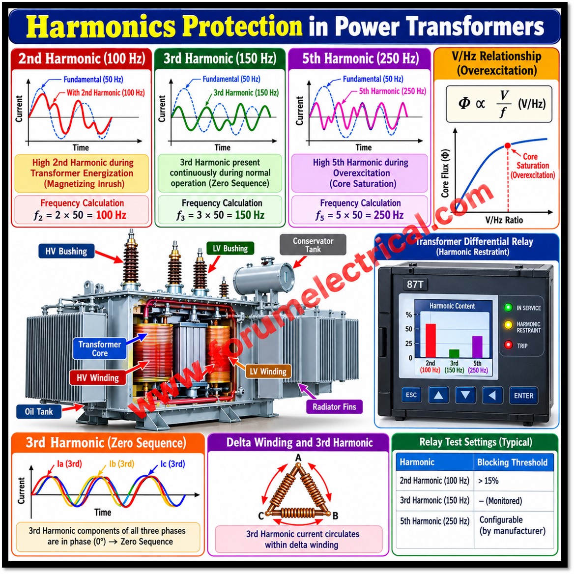
1. What is 2nd Harmonic?
2nd harmonic is a frequency component whose frequency is exactly twice the fundamental frequency.
For a 50 Hz power system, the fundamental is 50 Hz and so the 2nd harmonic is 100 Hz.
2. When is the 2nd Harmonic mainly produced?
2nd harmonic is mainly generated during transformer magnetizing inrush (when the transformer is first energized) and it is used by the Differential Relay (ANSI 87T) to distinguish inrush current from an internal fault.
3. Why does inrush current contain a large 2nd Harmonic component?
When a transformer is energized and a large magnetizing current flows to establish the magnetic flux in the core.
During this transient, the core operates in the saturation region which distorts the magnetizing current waveform heavily and this distortion contains a significant amount of 2nd harmonic (100 Hz).
4. How does the Differential Relay use the 2nd Harmonic?
The relay continuously measures the harmonic content of the differential current.
If the percentage of 2nd harmonic exceeds the preset blocking level the relay recognizes the condition as magnetizing inrush & blocks the differential trip.
5. What is the relay step-by-step operating logic for 2nd Harmonic blocking?
- The relay use to measures the differential current.
- It usually separates the current into the fundamental component (50 Hz) & the 2nd harmonic component (100 Hz).
- It calculates the harmonic ratio.
- If the 2nd harmonic ratio is greater than the relay setting, the differential trip is blocked.
- If the ratio is lower than the setting, the differential relay operates normally (trips on a genuine fault).
6. How is the 2nd Harmonic Ratio calculated?
2nd Harmonic Ratio (%) = (2nd Harmonic Current ÷ Fundamental Current) x 100
7. What is the testing procedure for verifying 2nd Harmonic blocking?
- Enable differential protection.
- Inject differential current using a relay test set.
- Add the required 2nd harmonic component.
- Verify the relay blocks the trip when the harmonic ratio exceeds the blocking setting.
- Reduce the harmonic ratio below the setting.
- Verify the relay then issues a trip.
8. What is the 3rd Harmonic?
A frequency component whose frequency is 3 times the fundamental frequency.
For a 50 Hz system: 3rd Harmonic = 3 x 50 = 150 Hz.
9. What causes the 3rd Harmonic?
3rd harmonic is generated due to the non-linear magnetizing characteristics of the transformer (or) generator core.
When the core operates in the non-linear region of the B-H curve, the magnetizing current is no longer purely sinusoidal that is generating harmonic components and one of the most significant being the 3rd harmonic.
10. How is the 3rd Harmonic different from the 2nd Harmonic in terms of occurrence?
Unlike the 2nd harmonic which is mainly associated with transformer energization (a transient event), the 3rd harmonic is present continuously during normal operation at a low level which is varying with the magnetic condition of the core.
11. What are the key characteristics of the 3rd Harmonic?
- Frequency = 150 Hz
- It is a third-order harmonic component.
- Classified as a Zero Sequence Harmonic.
- The 3rd harmonic components of all three phases are in phase with each other.
- It is continuously produced by the magnetic characteristics of the core.
12. Why is the 3rd Harmonic called a “Zero Sequence Harmonic”? Show the calculation.
In a balanced three-phase system:
Phase A = 0°, Phase B = −120°, Phase C = +120°. For the 3rd harmonic: 3×0° = 0°, 3 x (−120°) = −360° = 0°, 3×(+120°) = +360° = 0°.
Thus, the 3rd harmonic components of all three phases become 0°, meaning they are all in phase and this is why it is called a zero-sequence harmonic.
13. How does a delta winding behave with 3rd Harmonic currents?
A delta winding provides a closed path for zero-sequence currents. When 3rd harmonic current is produced inside the transformer, it circulates within the delta winding instead of flowing into the external power system.
This circulating current helps prevent propagation of 3rd harmonic currents to the transmission network and improves the voltage waveform.
14. How does overexcitation lead to 5th Harmonic generation?
As magnetic flux increases, the core enters the saturation region, causing the magnetizing current waveform to become highly distorted.
This distorted current contains a significant amount of 5th harmonic (250 Hz).
A high 5th harmonic is therefore an indication of core overexcitation rather than an internal winding fault.
15. What is the Overexcitation Principle (V/Hz relationship)?
Magnetic flux inside a transformer is proportional to the voltage-to-frequency ratio (V/Hz)
Where
V is applied voltage and f is system frequency.
If voltage increases or frequency decreases, the V/Hz ratio increases; as a result, core flux increases, the core enters saturation, magnetizing current becomes highly distorted and 5th harmonic content increases.
16. What is the relay operating principle for the 5th Harmonic?
The relay continuously measures the differential current and performs harmonic analysis, separating it into the fundamental component (50 Hz) and harmonic components (2nd, 3rd, 5th, etc.).
It continuously monitors the percentage of 5th harmonic; a high 5th harmonic content indicates that the transformer is operating under overexcitation.
Depending on the relay manufacturer and protection philosophy, the relay may apply 5th harmonic restraint (or) blocking to avoid unwanted differential operation.
17. What actions can the relay take when 5th Harmonic exceeds the threshold?
The relay continuously compares the measured 5th harmonic level with the configured setting. If it exceeds the threshold, the relay recognizes overexcitation and, depending on design, may:
- Apply differential restraint.
- Apply harmonic blocking.
- Prevent unnecessary differential tripping.
18. What are the main applications of the 5th Harmonic?
- Transformer overexcitation detection.
- Harmonic analysis.
- Differential protection restraint (on supported relay models).
- Power quality monitoring.
19. How does the 4th Harmonic differ from the 2nd, 3rd and 5th Harmonics?
The 4th harmonic is a fourth-order harmonic component whose frequency is 4 times the fundamental frequency.
In a 50 Hz power system, its frequency is:
f4 = 4 x 50 = 200Hz
- 2nd harmonic (100 Hz): Commonly associated with transformer magnetizing inrush and used by differential relays for inrush restraint or blocking.
- 3rd harmonic (150 Hz): A zero-sequence harmonic that may circulate in delta-connected windings.
- 4th harmonic (200 Hz): An even-order harmonic that can arise from waveform asymmetry or nonlinear operating conditions, but it is not a standard universal indicator of transformer inrush.
- 5th harmonic (250 Hz): May increase during transformer core saturation and overexcitation although it is not a definitive indicator on its own.
20. How can harmonic restraint be tested in a transformer differential protection relay?
Harmonic restraint can be tested using a compatible secondary-injection relay test set.
- Verify the relay settings and follow the manufacturer’s test procedure.
- Inject the required fundamental-frequency differential current.
- Add a controlled 2nd harmonic component and gradually increase its percentage.
- Verify that the relay applies the configured inrush restraint or blocking when the threshold is crossed.
- Reduce the harmonic percentage below the threshold and verify the expected relay response.
- Repeat with a 5th harmonic component if the relay supports overexcitation restraint or blocking.
- Record the measured pickup, restraint, blocking, and trip behavior.

