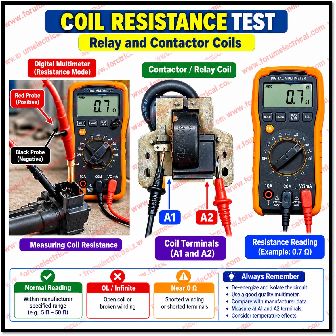
- Relay and
- Contactor coils
are the electromagnetic basis of
- Automation circuits,
- Control panels and
- Motor starters.
When a contactor fails to pull in, hums loudly (or) chatters, the coil is a common cause.
A resistance test is a fast, inexpensive check that can confirm or rule out a coil fault before the component is replaced.
This post explains the procedure, how to interpret each reading, and the precautions needed for reliable results.
Principle of the Test
A coil is a length of insulated copper wire wound on a bobbin.
Its DC resistance depends on wire gauge, number of turns and temperature. Because a healthy coil has a stable, repeatable resistance, an ohmmeter reading reveals winding damage.
The reading of infinite resistance is indicative of an interrupted winding, while the reading is reduced by turns that have short circuited together.
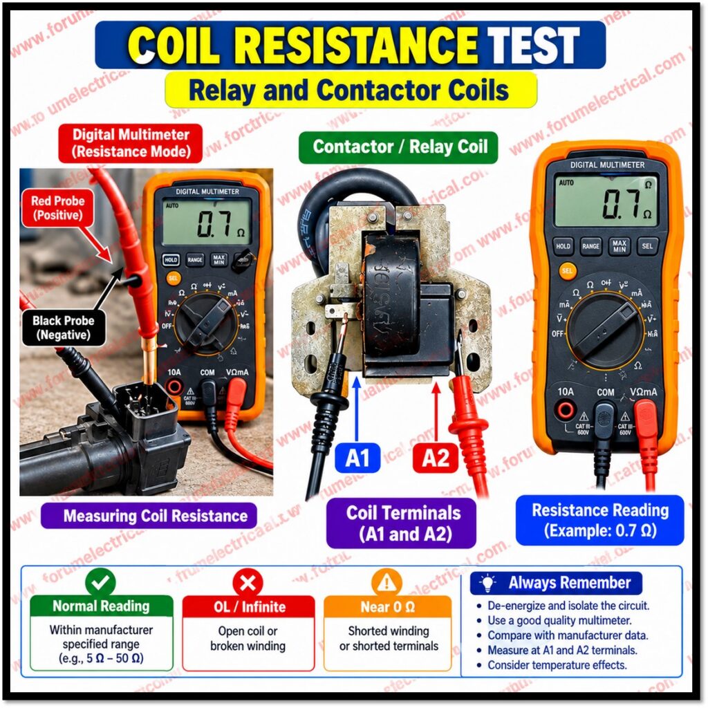
The winding terminals are typically identified as A1 and A2.
Impedance is not the same as resistance.
Since inductive reactance limits operational current, an AC coil’s DC resistance is much lower than the primary voltage divided by operating current.
Always compare the measurement with the manufacturer’s resistance figure, never with a calculated value.
Step-1: Safely De-energize the Circuit
- Isolate the Supply: Switch off and open the upstream disconnect, then apply lockout/tagout according to site procedures.
- Verify Zero Voltage: Inspect the coil terminals & the control wiring in the surrounding area using a meter that is appropriately rated. Employ the test-prove-test method: verify the meter on an identified source, test the circuit and then verify the meter once more.
- Check for Foreign Voltages: Interlock circuits, external control supplies and PLC outputs may remain live even after the main supply is isolated.
- Isolate the Coil: Label at least one wire that is disconnected from A1 or A2. On the other side, incorrect readings and possible harm to delicate electronics could arise from the creation of parallel channels by bulbs, transformers, surge suppressors or electronic outputs.
- Wear Suitable PPE: Use insulated gloves and eye protection in accordance with the risk assessment for your workplace.
Step-2: Measure Resistance Between A1 and A2
Set the multimeter to the resistance (Ω) function. Touch the probe tips together and note the lead resistance, normally below 0.5 Ω; subtract it when measuring low resistance coils.
Place the probes firmly on A1 and A2, hold them steady and wait for the display to settle.
Record the value & compare it to the figure printed on the coil or the datasheet.
The high resistance coils values are distorted by parallel body resistance, therefore avoid touching both probe ends.
Interpreting the Results
| Reading | Detail | Recommended Action |
|---|---|---|
| OL / infinite | Open winding (or) broken internal connection. | Replace the coil (or) relay |
| Near 0 Ω | Shorted winding (or) shorted terminals. | Replace the coil and inspect wiring |
| Within specification | Winding likely healthy. | Investigate supply, contacts and mechanics. |
| Above Expectations | High resistance malfunction (or) a damaged winding. | Clean terminals, retest, then replace. |
| Unstable reading | Intermittent break (or) poor contact. | Reseat probes and replace if it persists. |
Identifying Open Coil (OL)
An open coil displays OL, meaning the reading exceeds the meter’s range and no continuous conductor exists between A1 and A2.
Typical causes include a burned-through winding, a fractured fine wire at a terminal joint or mechanical damage.
Before discarding the coil, reseat the probes and make sure the meter is not set to continuity or diode.
A correct OL indicates that the coil cannot energize & should be replaced.
If the device is a plug-in relay, check the socket pins for burn marks (or) looseness as a damaged socket can resemble an open coil.
An intermittent break can be detected by carefully extending the leads while watching the display.
Recognizing Shorted Coil
A reading close to zero indicates a short between the terminals or across most of the winding.
Overheating, insulation breakdown or contamination are common causes.
Bridging 5% of turns lowers resistance by 5%, which is acceptable for partial shorts.
Suspect this if the coil warms up, sounds or blows its control fuse despite good resistance.
The most reliable test is to compare the reading to a new coil that is identical.
Checking the Specified Range
Coil resistance varies widely with voltage rating and design, from a few ohms for low-voltage DC coils to several kilohms for high-voltage AC coils, so no universal value exists.
Use the manufacturer’s datasheet.
If no tolerance is given, about ±10 percent is a common practical allowance.
Temperature is important.
Copper resistance rises roughly 0.4 percent per °C, so a coil that has just been running may read several percent higher than when cold.
Test at ambient temperature whenever possible.
A value inside the range suggests the winding is sound, so continue troubleshooting the control voltage, overload contacts, start/stop circuit and mechanical movement of the armature.
Practical Multimeter Features
- Use a Quality Meter: Choose a category-rated meter with good low-ohmic accuracy.
- Test at the Coil: To avoid wiring errors, measure directly at A1 and A2 rather than at remote connections.
- Clean the Contacts: Oxidation or dirt on terminals can add false resistance.
- Watch DC Coils: Coils with the freewheeling diodes or suppressors can read differently when probe polarity is reversed.
- Know Electronic Coils: Wide-range (or) integrated-electronics coils do not behave as simple windings; follow the datasheet.
- Record Readings: Keep baseline values for critical equipment to detect gradual deterioration.
- Check Insulation: If the resistance is normal yet the circuit trips, an insulation test to earth may be required.
- Verify Replacements: Before installing a new coil, make sure it meets the specifications and voltage rating.
Conclusion
A coil resistance test takes minutes but yields results: OL implies an open winding, close to zero indicates a short and within specification leads study.
Measure A1 and A2 after de-energizing & isolating the coil correctly and comparing results with manufacturer data at a consistent temperature, technicians avoid unnecessary part replacement and restore equipment faster and more safely.

