
- What is a Magnetic Contactor?
- Working Principle of a Magnetic Contactor
- Construction of the Magnetic Contactor
- How should the magnetic contactor be connected?
- Function of the Contactor
- Advantages of the Magnetic Contactor
- Disadvantages of the Magnetic Contactor
- Applications of the Magnetic Contactor
- Magnetic contactor parameter selection
- Magnetic Contactor Types
- Frequently Asked Questions about Magnetic Contactor
- 1). Why are contactors used in motors?
- 2). What does FLA on a contactor mean?
- 3). How to determine a contactor is broken?
- 4). Is it possible to replace the contactor that handles 30 amps with one that handles 40 amps? or to a greater extent?
- 5). What is the difference between a magnetic contactor and a relay?
- 6). What led to the contactor becoming stick or failing altogether?
What is a Magnetic Contactor?
A magnetic contactor is a device or switch that operates magnetically to close or open an electric circuit as needed.
A magnetic contactor is an electromechanical device used to establish or interrupt the flow of current in either the power or control circuits.
Working Principle of a Magnetic Contactor
A magnetic contactor is made up of a magnetic core (core and armature) and a coil that generates a strong magnetic field enough to overcome the forces of the springs that hold the two portions of the core apart. One of these components, typically the armature, is integrally coupled to the device and is in charge of activating the electrical contacts.
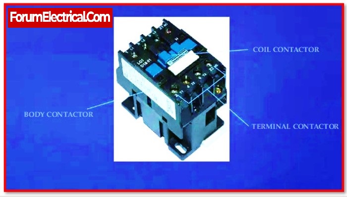
Construction of the Magnetic Contactor
A magnetic contactor’s design is simple. The following are the device’s components.
- Core
- Armature
- Coil or Electromagnet
- Contact
- Coil terminals
- Spring
- Enclosure
1). Core
The core is comprised of silicon steel sheets that are securely linked together to prevent energy losses caused by current parasite circulation. Its purpose is to house the coil, concentrate the magnetic flux it generates, and attract the armour.
2). Armature
The armature is the electromagnet’s moving part. It is extremely similar to the nucleus, however unlike it, it lacks turns of shade. Its primary role is to close the magnetic circuit and drag the mobile contacts with it.
3). Coil or Electromagnet
The electromagnet’s force of attraction is determined by the magnetic flux that passes through it. An excitation coil placed in one of the columns of the electromagnet core generates this flux. The reels can be wound on an insulated resin spool.
Enamelled copper wire with a circular section is commonly used for coil construction, and the procedures for making it are well known.
The coil characteristics are visible on the coil: voltage, current class, and frequency in the case of alternating current.
4). Contact
Contacts are classified into two categories.
a). Main Contacts and
b). Auxiliary contacts
a). Main contacts
The main contacts or poles are the contacts that act directly on the load to be managed.
The main contacts are linked to the governing circuit. Ensures the establishment and interruption of main currents, and depending on the number of current paths (bipolar, tripolar, tetrapolar, etc.), manoeuvres (movement) are carried out concurrently on all tracks.
b). Auxiliary contacts
Auxiliary contacts are classified into two types.
- Normally Open (NO contact)
- Normally Closed (NC contact)
These two types of contacts are part of the contactor’s auxiliary circuit. It ensures the automation equipment’s self-supply, controls, contact interlocks, and signalling.
The circuit between the network and the receiver is established when the contactor coil is activated by current flow, causing its core to move and drag its main and auxiliary contacts.
5). Coil Terminals
The voltage of the incoming power as well as whether the power is derived from a single-phase or three-phase source determines the size of coil terminals as well as the number of terminals.
6). Spring
The spring’s function is to keep the contacts open, which in turn ensures that the load does not get any electricity. Either it will pull from the other side or it will push the moveable contacts further away from the yoke. There are other models that are created specifically for vertical installation, and in those models, gravity might take the role of the spring.
7). Enclosure
The enclosure ensures that all of the components remain electrically isolated and protects users against unintentional exposure. Plastic, Bakelite, or Nylon 6 are the three materials that are used to construct the enclosure.
How should the magnetic contactor be connected?
Before connecting, check the label value is appropriate for the system to which are connected before connecting the equipment. Then look for the A1 and A2 terminals. These terminals are known as coil terminals. When the coil is energised, the contactor’s main power contact closes. Connect A1’s phase (+) and A2’s neutral (-).
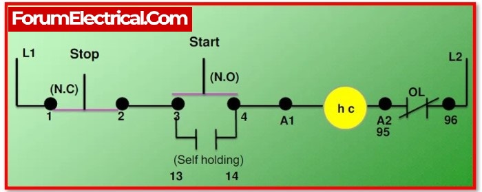
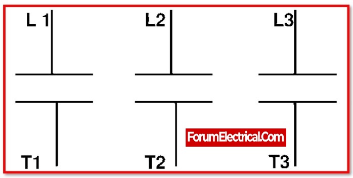
Connect L1, L2, and L3 to the main power connectors. NO and NC are the auxiliary contact inputs. Assistive contacts send positional information about the contactor to a remote device (such as opening or shutting information).
Function of the Contactor
When an electromagnetic coil is energised, it produces an electromagnetic field. As mentioned in construction, the movable contact of a contactor is coupled to the armature (metallic rod) of an electromagnet.
When an electromagnetic field is created, the armature experiences a pull towards the fixed contact. The force produced by the coil exceeds the force produced by the spring. Both contacts will stay in this state as long as the coil is not de-energized.
When the coil is de-energized, the electromagnetic force becomes zero, and the armature pulls back due to spring force. And then return to normal (OFF position). The contactors are developed for immediate ON/OFF operation.
The contactor coil’s input can be AC or DC, and in some circumstances, the universal coil is employed as an electromagnetic coil. The universal coils work on both alternating current and direct current. A tiny amount of power is lost in the contacts, which is reduced using an economizer circuit.
An arc is formed between the contacts as they are made and broken. Because it raises the temperature of the contacts, this arc may shorten the life of the contactor. Arc produces hazardous gases such as mono-oxide. As a result, different ways are employed to control and extinguish arcs.
The contactors are chosen based on the load current and voltage, the voltage control range, and the application category. Users can use an ohm-meter to determine if the connection of contacts is open or closed. Connect the ohmmeter between the input and output contacts; if the meter reads infinite, the contacts are open; if it reads zero, the contacts are closed.
Advantages of the Magnetic Contactor
- The ability to control a machine completely from many control points or stations.
- Circuits connected to currents can be controlled at extremely high currents.
- Technical personnel safety.
- Given that the manoeuvres (movement) are performed from locations remote from the motor or other sorts of loads.
- The command devices manipulate currents and voltages that are or may be modest.
- Control and automation of complex processes in equipment and machines.
Disadvantages of the Magnetic Contactor
- Magnetic contactors will not malfunction if they are properly selected and utilised under normal operating conditions. Contact wear and coil burn are the most typical issues.
- If a large amount current is sent via the power connections, they will become heated and stick together.
- A magnetic contactor, unlike a circuit breaker, is not a safety device. When an overcurrent current flows through a circuit breaker, it causes it to trip. Overcurrent flowing through the magnetic contactors, on the other hand, causes the main contacts to stick.
- Similarly, if the voltage provided to the coil terminal is not nominal, the coil will burn. As a result, nominal voltage and current values must be provided to the main contacts and coil.
- To improve system protection, protection devices such as overload relays and fuses must be employed in conjunction with the contactor.
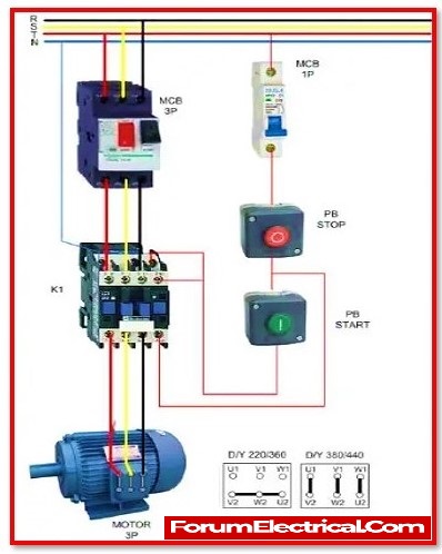
Applications of the Magnetic Contactor
- The motor starter is the most common use for a contactor. It is utilised for industrial motor overload and short circuit protection.
- Contactors are used to automate lighting in industrial, commercial, and residential applications. Latch type relays are employed in this application. Two coils are utilised in this sort of relay. One is for open contact, and the other is for close contact.
- Single pole contactors are utilised to power the vehicle’s 12VDC load.
- The usage of contactors in conjunction with a circuit breaker ensures the safety of load operation in industries. In this application, it is used to switch a load quickly.
- It is employed in mercury relays as well as mercury-wetted relays.
- To run 240VAC loads such as air conditioners, two-pole (3-wire, 1-phase) contactors are employed.
Magnetic contactor parameter selection
The following technical parameters influence the selection of a magnetic contactor:
- The type of load i.e., motor, heating, lighting, and air conditioning
- Rated current and rated power.
- Voltage used in operation.
- Voltage control.
- The total number of poles.
- Internal auxiliary contacts availability.
Magnetic Contactor Types
Magnetic contactors are classified into different categories.
- Knife Blade Switch Contactor
- Manual Contactor
- Alternating Current (AC) Contactor and
- Direct Current (DC)Contactor
1). Knife Blade Switch Contactor
Electric motors turned on and off with this contactor. It’s a lever-equipped metal strip. Metal strips are pulled up and down using the lever. It’s manual. It’s hard to manually switch on and off quickly. Wearing out contacts is possible.
In large motors whole load current passes through the contacts, thus it’s high. Arc generation between contacts is difficult to quench in this condition. The second issue is power loss. Due to the high current, the connections will waste a lot of power.
Safety is the third issue. Therefore, this form of contactor needs modification. Due to moisture damage, this contactor has a short lifespan. Due to operational issues, this contactor is rarely used.
2). Manual Contactor
Manual Contactor is also called double break contactor. This contactor is safe for smaller units. It lets to use more current in less area. Double break contacts split the connection into two sets. As its term indicates, manual control is required. The operator manually turns on and off.
This contactor is the most advanced and so called automatic electromagnetic contactor. Turning on and off the load requires a simple control circuit. This contactor is safer than manual contactors. Industrial applications use this contactor most. Electromechanically, it connects load and power source with a small current.
3). Alternating Current (AC) Contactor
Contactors used with alternating current are classified into four types based on the nature of the load, and their applications are as follows:
- AC 1 magnetic contactor
- AC 2 magnetic contactor
- AC 3 magnetic contactor
- AC 4 magnetic contactor
a). AC 1 Magnetic Contactor
This type of contactor is useful for resistive loads such as heaters and electrical furnaces, as well as non-inductive or mildly inductive loads, whose power factor ranges from 0.95 to 1.
b). AC 2 Magnetic Contactor
For the starting of motors with slip rings, it is used. As a slip ring motor, this component is suitable for usage with loads that retract. They utilise high torque current applications the most of the time.
c). AC 3 Magnetic Contactor
AC-3 Magnetic Contactor utilised in squirrel cage induction motors for the purpose of performing disconnection operations while the motor is operating at its maximum speed. The breaking current is within acceptable limits.
d). AC 4 Magnetic Contactor
AC-4 magnetic contactor is used to start and stop an induction motor with a cage. Squirrel-stopping in the starting, jogging, and reversing by reverse.
4). Direct Current (DC) Contactor
The list consists of the various types of DC contactors.
- DC 1 magnetic contactor
- DC 2 magnetic contactor
- DC 3 magnetic contactor
a). DC 1 Magnetic Contactor
DC-1 magnetic contactor is appropriate for inductive and rather non-inductive loads, as well as resistance furnaces and heaters.
b). DC 2 Magnetic Contactor
The DC-2 Magnetic Contactor Dynamic braking, in which the motor is disconnected while it is spinning rapidly in shunt motors’s starting, plugging, inching.
c). DC 3 Magnetic Contactor
The DC-3 Magnetic Contactor is used for dynamic braking, jogging, reversing with reverse gear, and starting series motors.
Frequently Asked Questions about Magnetic Contactor
1). Why are contactors used in motors?
The motor contactor allows one to remotely turn on and off the motor. The contactor can be used to start and stop the motor.
2). What does FLA on a contactor mean?
Full Load Amps (F.L.A.) is the motor’s designed output current at the rated horsepower. The ampere of the motor that can be connected to the contactor is indicated by FLA on the contactor.
3). How to determine a contactor is broken?
A poor contactor is characterised by buzzing and vibration during contact, as well as warming of the body.
4). Is it possible to replace the contactor that handles 30 amps with one that handles 40 amps? or to a greater extent?
A more advanced contactor variant is available for replacement if necessary. This choice prices at a higher cost.
5). What is the difference between a magnetic contactor and a relay?
A contactor connects two poles without a common circuit, whereas a relay has a common contact that connects to a neutral state. Furthermore, contactors are generally rated for up to 1000V, whereas relays are typically rated for just 250V.
6). What led to the contactor becoming stick or failing altogether?
- An excessive current is flowing through the contacts.
- The coil can be subjected to a low or high voltage.
- The presence of dust, corrosion, or vibration in the environment
- The wrong product was selected.
- Changes in the voltage and other transients.
- Ambient temperature.
- The electromotive force causes short circuits.