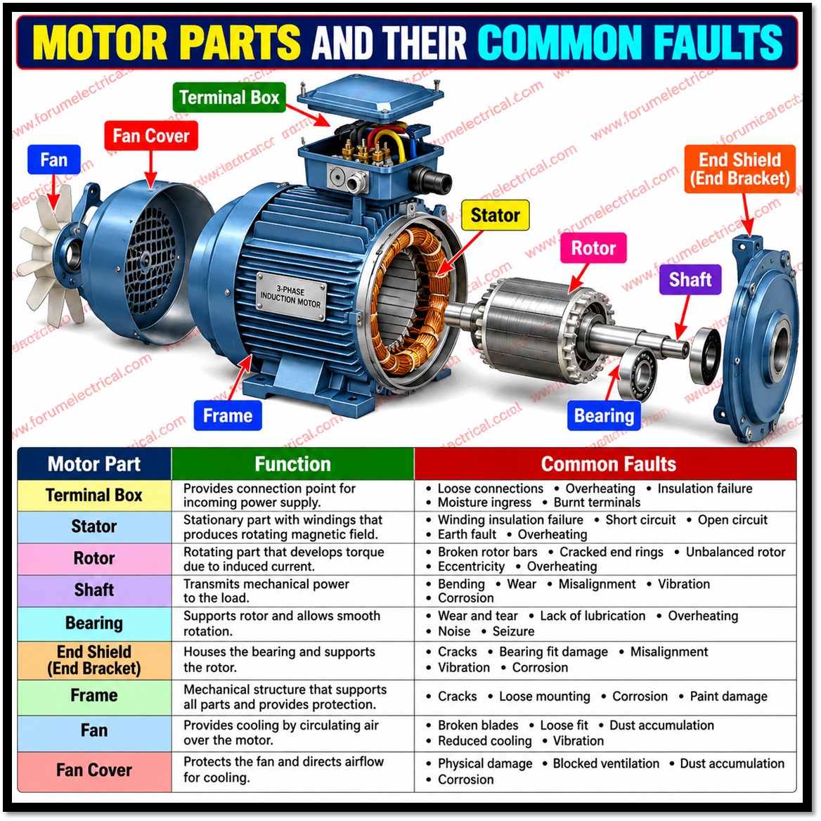
Understanding how motor components fail is essential for anyone who installs, maintains or tests rotating machinery.
Knowing each part’s failure modes allows a technician to select the right corrective action before a minor defect becomes a costly breakdown.
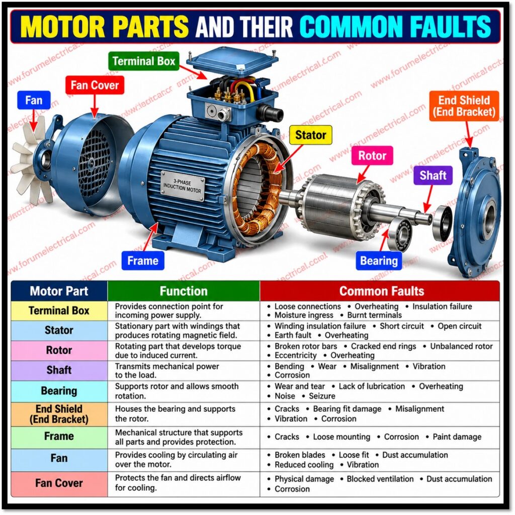
This analysis reviews the shaft, rotor, stator, bearings and insulation, followed by 2 key electrical tests: the hipot test and the winding resistance test.
Shaft
The shaft transmits torque and rotation from the rotor to the driven load.
Its most common problem is misalignment, which may be angular (shaft centrelines meet at an angle) or parallel (centrelines are offset).
Misalignment overloads the bearings, heats couplings and shortens bearing life well below its design value.
Vibration analysis is the standard detection method: misalignment typically produces elevated vibration at one and two times running speed, often with a strong axial component.
Laser or dial-indicator alignment during installation, plus periodic checks of load and running current, limits wear and tear.
Rotor
The rotor converts electromagnetic energy into mechanical rotation.
In a squirrel-cage induction motor, the main faults are broken or cracked rotor bars and damaged end rings.
These arise from repeated hard starts, overload, thermal stress and casting defects.
Causes include
- Reduced torque,
- Speed fluctuation,
- Increased vibration and
- Sidebands
around the supply frequency in motor current signature analysis (MCSA).
Normal wear & fatigue damage the rotor’s cooling fan, reducing airflow & increasing operating temperature.
Without preventive maintenance, temperature cycling and corrosion erode rotor conductors till they fracture. Limiting starts per hour and avoiding overload are the main protections.
Stator
The stator is the stationary part of the motor, consisting of a laminated steel core carrying the windings.
Typical faults are
- Turn-to-turn shorts,
- Phase-to-phase shorts,
- Winding-to-ground faults and
- Open circuits.
Signs include power outages, difficulties starting, overheating, uneven phase currents, and protection trips.
Clarification: the source mentions a pick-up coil and a battery.
Those terms apply to the stator of an alternator or magneto charging system, such as in motorcycles, where the stator generates alternating current that is rectified to charge a battery.
In this both the source coils and the pick-up coil should be tested. Loose or corroded connectors deserve replacement, because a poor connection generates heat, which damages the connector, causes a short circuit and can burn the stator and neighbouring electrical parts.
Bearings
A three-phase induction motor normally has two bearing sets, at the drive end and non-drive end, supporting the shaft within the housing.
Each rolling-element bearing comprises an inner race, an outer race and a set of rolling elements (balls or rollers) held by a cage.
Damage to these parts causes noise, heat and vibration, and eventually the motor seizes.
Common causes are
- Inadequate or excessive lubrication,
- Contamination,
- Overload,
- Misalignment and
- In inverter-driven motors,
- Electrical discharge currents that pit the races (fluting).
Vibration measurement is the primary check, supported by temperature and ultrasound monitoring.
Insulation Breakdown
Insulation degradation and eventual breakdown, including flashover, is among the most frequent causes of electrical equipment failure.
Winding insulation consists of enamels, resins, varnishes or polymers.
Thermal, electrical, mechanical and environmental stresses (heat, voltage spikes, vibration, moisture and contamination) gradually reduce its dielectric strength.
A widely used rule of thumb is that insulation life roughly halves for each 10 °C of sustained temperature rise above its rating.
Clarification: the inter-laminar coating mentioned in the source refers to the thin insulating layer between steel laminations in cores of motors and transformers which limits eddy-current losses.
It is distinct from the winding insulation that separates conductors from each other and from ground.
Hipot Test
A hipot (high-potential) test also called a dielectric strength test, checks for weaknesses in cable or winding insulation.
Strictly speaking, it applies a high voltage, not a current, between the energised circuits (windings) and the frame or ground, while the instrument measures the resulting leakage current.
The test voltage depends on the motor and its rated voltage; a common factory value for AC windings is twice the rated voltage plus 1000 V, while in-service tests use a reduced level.
Only readings below the recommended minimum indicate damaged insulation; higher readings are better. IEEE Std 43 gives a minimum of 1 MΩ plus 1 MΩ per kV of rated voltage, corrected to 40 °C and a polarisation index (10-minute divided by 1-minute reading) of at least 2.0 for most insulation classes.
Always discharge the winding after testing.
Motor Winding Resistance Test
The winding resistance test is an offline test used to locate winding problems and it should be carried out whenever cracks or burns are seen (or) a burning smell is noticed.
The procedure is as follows:
- Prepare: Isolate and lock out the motor, then clean the windings with low-pressure dry compressed air and inspect them visually.
- Set up the Meter: Set up the meter by selecting the lowest resistance range & placing the leads together to validate a 0 ohm reading & adjust for lead resistance.
- Measure: Record resistance across each pair of terminals & compare the 3 readings to the nameplate (or) manufacturer data.
- Interpret: An open circuit shows as infinite resistance, a shorted turn as a lower value & a loose connection (or) damaged conductor as a higher value. Phase imbalance beyond about 3 to 5% warrants analysis.
Clarification: ordinary multimeters have limited accuracy for low-resistance windings, so a micro-ohmmeter (or) Kelvin bridge is preferred.
Turn-to-turn faults that barely change resistance are better detected with a surge comparison test.
Summary of Faults
| Component | Typical fault | Main detection method |
|---|---|---|
| Shaft | Misalignment, bending | Vibration analysis, laser alignment |
| Rotor | Broken bars, cracks | MCSA, vibration |
| Stator | Shorted or open windings | Resistance, surge, megger tests |
| Bearings | Race or ball damage | Vibration, temperature, ultrasound |
| Insulation | Degradation, flashover | Megger, polarisation index, hipot |
Conclusion
Each motor component fails in recognisable ways, and most faults give early warning through vibration, heat, noise, current imbalance or falling insulation resistance.
Scheduled condition monitoring and electrical testing allow correction before an unplanned outage.
Proper alignment, lubrication, clean and cool operation and secure electrical connections remain the most effective protection for any motor.

