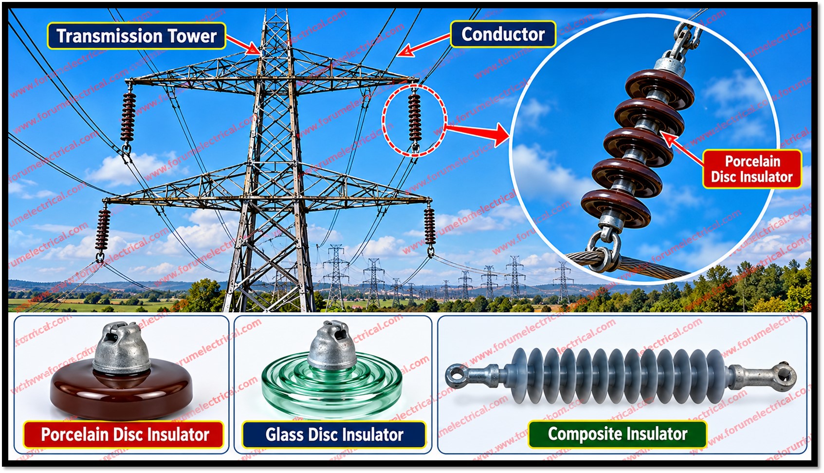
The proper operation of a transmission (or) distribution line depends heavily on the proper working of its insulators.
A good insulator must satisfy three requirements.
a). First, it requires good mechanical strength to withstand mechanical loads and stresses.
b). Second, it needs high dielectric strength to withstand operating voltages and flashover voltages.
c). Third, it should be free from pores (or) voids which may damage it.
To ensure required performance, each insulator has to undergo various tests.
IEC 60383-1:2023 specifies the test methods and requirements for ceramic and glass insulator units used on overhead power lines.
- Classification of Tests
- Flashover Tests
- 1). Power Frequency Dry Flashover Test
- 2). Power Frequency Wet Flashover Test (Rain Test)
- 3). Impulse Frequency Flashover Test
- Performance Tests
- 1). Temperature Cycle Test
- 2). Puncture Voltage Test
- 3). Mechanical Strength Test
- 4). Electro-Mechanical Test
- 5). Porosity Test
- Routine Tests
- 1). High Voltage Test
- 2). Proof Load Test
- 3). Corrosion Test
- Summary of Test Parameters
- Analysis
Classification of Tests
The tests carried out on overhead line insulators fall into 3 groups, each addressing a different aspect of insulator quality:
- Flashover tests: verify electrical withstand capability in dry, wet and surge conditions.
- Performance tests: verify thermal, electrical, mechanical and material soundness.
- Routine tests: check each insulator for high-voltage withstand, load capacity and corrosion resistance.
Flashover Tests
Three flashover tests must be conducted before an insulator is said to have passed.
In each, the insulator is mounted in the same manner in which it will be used.
Flashover voltage is the voltage at which the air surrounding the insulator breaks down and becomes conductive.
1). Power Frequency Dry Flashover Test
A variable voltage source of power frequency is connected between the electrodes of the insulator and the voltage is raised gradually to a specified value.
This specified voltage is less than the minimum flashover voltage.
The insulator must withstand it for 1 minute without flashover.
2). Power Frequency Wet Flashover Test (Rain Test)
The set-up is the same as for the dry test but the insulator is also sprayed with water at an angle of 45° with precipitation not exceeding 5.08 mm/min.
The voltage is raised gradually to the specified value and held for 30 seconds or one minute while the insulator is observed for puncture (or) breakdown.
When the voltage is held for one minute, the test is also called the one-minute rain test.
3). Impulse Frequency Flashover Test
This test ensures that the insulator can sustain the high-voltage surges caused by lightning.
An impulse voltage generator, producing a very high voltage at a frequency of several hundred kilohertz, is connected to the insulator and the spark-over voltage is noted.
The ratio of impulse spark-over voltage to spark-over voltage at power frequency is the impulse ratio.
It should be approximately 1.4 for pin type insulators and 1.3 for suspension type insulators.
IEC 62217:2025 defines general test methods and acceptance criteria for polymeric high-voltage insulators.
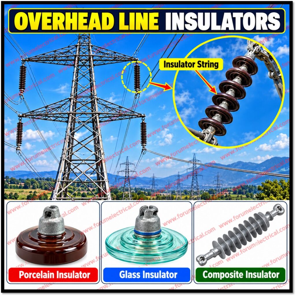
Performance Tests
1). Temperature Cycle Test
The insulator is heated in water at 70 °C for one hour and then immediately cooled at 7 °C for another hour.
This cycle is repeated three times.
The insulator is then dried and its glazing is examined thoroughly for damage or deterioration.
2). Puncture Voltage Test
This test determines the puncture voltage, the voltage at which the insulator starts to puncture.
The insulator is suspended in insulating oil and voltage is increased gradually until puncture occurs.
For suspension type insulators, this voltage is usually 30% higher than the dry flashover voltage.
3). Mechanical Strength Test
The insulator is subjected to 250% of the maximum working load for one minute, in order to determine its ultimate mechanical strength.
4). Electro-Mechanical Test
This test is conducted only on suspension type insulators.
A tensile stress of 250% of the maximum working tensile stress is applied, after which the insulator is tested at 75% of the dry spark-over voltage.
5). Porosity Test
A freshly manufactured sample is broken into pieces, which are immersed in a 0.5% to 1% alcohol solution of fuchsine dye under a pressure of 150 kg/cm² for several hours (say 24 hours).
The pieces are then removed and examined for dye penetration which indicates the degree of porosity.
Routine Tests
1). High Voltage Test
Usually carried out on pin insulators.
The insulator is inverted and placed in water up to the neck, the spindle hole is filled with water, and high voltage is applied for 5 minutes.
The insulator must remain undamaged.
2). Proof Load Test
Each insulator is subjected to a load 20% in excess of the working mechanical load (for example, tensile load) for one minute and must remain undamaged.
3). Corrosion Test
The insulator with its metal fitting is suspended in copper sulfate solution for one minute, then removed, wiped and cleaned.
The procedure is repeated 4 times.
The insulator is then examined for metal deposits, and there must be zero.
Summary of Test Parameters
| Test | Category | Key Acceptance Criterion |
|---|---|---|
| Power frequency dry flashover | Flashover | Specified voltage (below minimum flashover voltage) withstood for one minute. |
| Power frequency wet flashover | Flashover | Water spray at 45°, precipitation not above 5.08 mm/min; 30 s or one minute. |
| Impulse flashover | Flashover | Impulse ratio about 1.4 (pin type), 1.3 (suspension type). |
| Temperature cycle | Performance | 70 °C for 1 h, then 7 °C for 1 h; three cycles; no glaze damage. |
| Puncture voltage | Performance | In insulating oil; about 30% above dry flashover voltage (suspension type). |
| Mechanical strength | Performance | 250% of maximum working load for one minute. |
| Electro-mechanical | Performance; suspension type only | 250% of maximum working tensile stress, then 75% of dry spark-over voltage. |
| Porosity | Performance | Fuchsine dye, 150 kg/cm², about 24 h; dye penetration examined. |
| High voltage | Routine; usually pin type | Water to neck, 5 minutes; no damage. |
| Proof load | Routine | 20% above working mechanical load for one minute; no damage. |
| Corrosion | Routine | Copper sulfate, one minute, four repetitions; zero metal deposits. |
Analysis
The tests together cover every property required of a good insulator.
Dielectric strength is checked by the 3 flashover tests and the puncture test, which together cover dry, wet and lightning-surge conditions.
Mechanical strength is checked by the mechanical strength test, the electro-mechanical test and the proof load test.
Freedom from pores and voids is checked by the porosity test, while the temperature cycle and corrosion tests examine glazing integrity and metal fittings.
The percentages also show a clear pattern.
Routine tests apply a modest overload of 20% to every unit whereas performance tests apply 250% to sample units to establish ultimate strength.
The puncture voltage of suspension insulators being usually 30% above the dry flashover voltage implies that the surrounding air breaks down before the insulator body is punctured.

