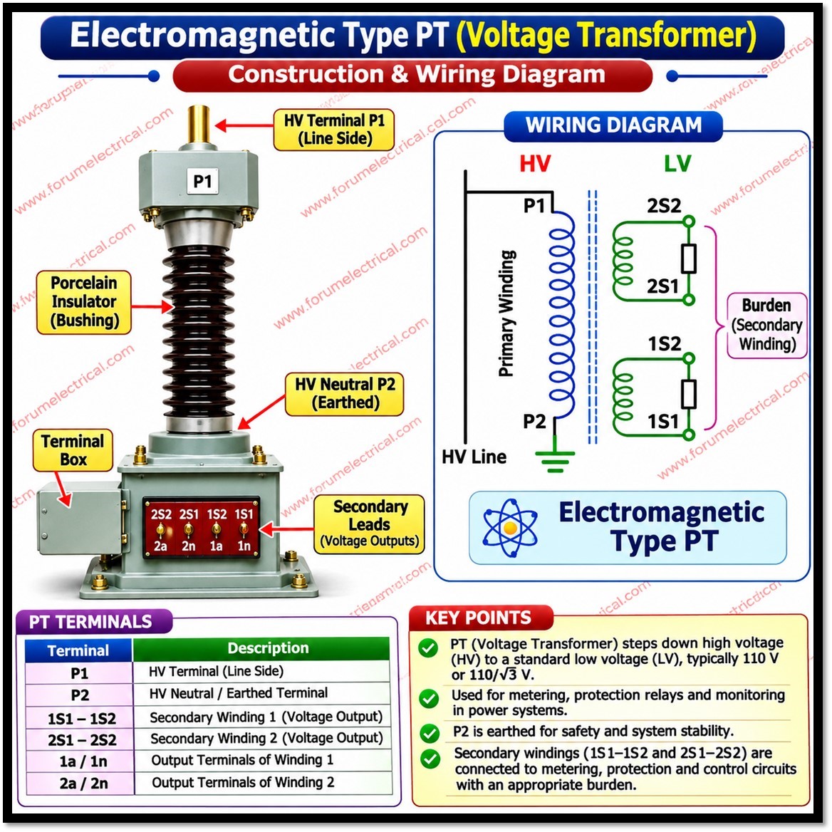
Power systems operate at voltages ranging from a few kilovolts (kV in distribution networks to several hundred kilovolts in transmission grids.
1). Meters,
2). Protection relays and
3). Control devices
are designed for low, standardized voltages.
Connecting them directly to a high-voltage (HV) line would be unsafe for personnel and would require instruments with impractically large insulation.
To solve this, engineers use an instrument transformer called the Potential Transformer (PT) which also known as a Voltage Transformer (VT).
- What is a Potential Transformer?
- Standard Secondary Voltages
- Working Principle of Potential Transformer
- Key Operating Characteristic
- Construction of Potential Transformer
- Types of Potential Transformers
- 1). Electromagnetic Potential Transformer
- 2). Capacitor Voltage Transformer (CVT)
- 3). Classification by Construction and Connection
- Voltage Ratio
- Solved Example
- Additional Examples
- Main Functions of PT
- Why PT is Important?
- Accuracy, Errors and Accuracy Classes
- Sources of Error
- Typical Accuracy Classes (IEC 61869-3)
- Burden (VA Rating)
- Indicative Burden Calculation
- Phasor Diagram of Potential Transformer (PT)
- Typical Applications of Potential Transformer
- Comparison: Potential Transformer vs Current Transformer
- Installation and Safety Considerations
- Checklist of Potential Transformer (PT)
- Conclusion
A PT steps the high system voltage down to a safe, standardized secondary voltage while keeping the secondary voltage accurately proportional to the primary voltage, in both magnitude and phase for measurement and protection.
What is a Potential Transformer?
A Potential Transformer is an instrument transformer that reduces a high primary voltage to a lower and standard secondary voltage through electromagnetic induction.
The reduced voltage is supplied to:
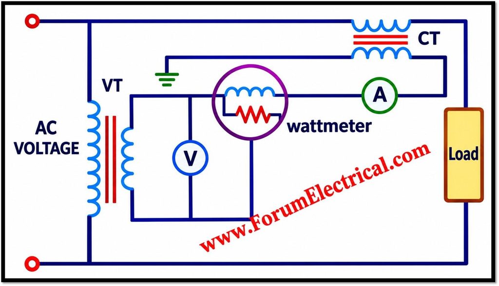
- Measuring instruments (voltmeters, wattmeters, power-factor meters)
- Protection relays (overvoltage, undervoltage, distance, directional and differential schemes)
- Energy meters (tariff and revenue metering)
- Control, synchronizing and SCADA equipment
Standard Secondary Voltages
The most common rated secondary voltages are 110 V and 63.5 V depending on the application and connection:
| Secondary Voltage | Meaning | Typical Use |
|---|---|---|
| 110 V | Line-to-line (phase-to-phase) rating. | PTs connected between two phases (or) three-phase PTs. |
| 63.5 V (110 / √3 ≈ 63.5 V) | Line-to-neutral (phase-to-earth) rating. | Single-phase PTs connected phase-to-earth in three-phase systems. |
Single-phase PTs connected phase-to-earth are typically rated as (Primary / √3) / (110 / √3) V.
For Example:
11 kV / √3 : 110 V / √3
In North American practice, 120 V and 69.3 V (120 / √3) secondaries are common and 110 V and 63.5 V are the values used in the application.
Working Principle of Potential Transformer
A PT works on the same principle as any transformer: mutual induction (Faraday’s law of electromagnetic induction).
It operates in the following sequence:
- Primary connection: The primary winding with many turns is connected across the high voltage (HV) line (in parallel with the system, i.e., shunt connection).
- Flux production: The primary current sets up an alternating magnetic flux in the laminated iron core.
- Induction: The core links this flux with the secondary winding which has far fewer turns that is inducing a proportionally lower EMF.
- Output: The secondary supplies an isolated, safe and proportional low voltage signal to meters and relays.
For an ideal transformer the relationship between voltages and turns is:
V₁ / V₂ = N₁ / N₂
Where
V₁ & V₂ – Primary and Secondary Voltages,
N₁ and N₂ – Numbers of Primary and Secondary Turns
Since N₁ is much greater than N₂ and V₂ is much smaller than V₁.
Key Operating Characteristic
A PT operates very close to no-load because the connected instruments draw only a small current.
Its secondary must never be short-circuited: a short circuit would draw a very large current that is causing excessive heating and likely damaging the PT. This is the opposite of a Current Transformer (CT) whose secondary must never be left open.
Construction of Potential Transformer
| Component | Description |
|---|---|
| Core | Laminated high-grade silicon steel (or similar) to reduce eddy-current and hysteresis losses and to keep magnetizing current low. |
| Primary winding | Large number of turns of fine conductor that is connected across the HV line and insulated for the full system voltage. |
| Secondary winding | Fewer turns of thicker conductor that is delivering the standard low voltage (e.g., 110 V or 110/√3 V). May have more than one winding (e.g., a measuring winding and a residual/open-delta winding). |
| Insulation | Oil, resin (cast epoxy), paper (or) SF₆ gas depending on voltage level and design. |
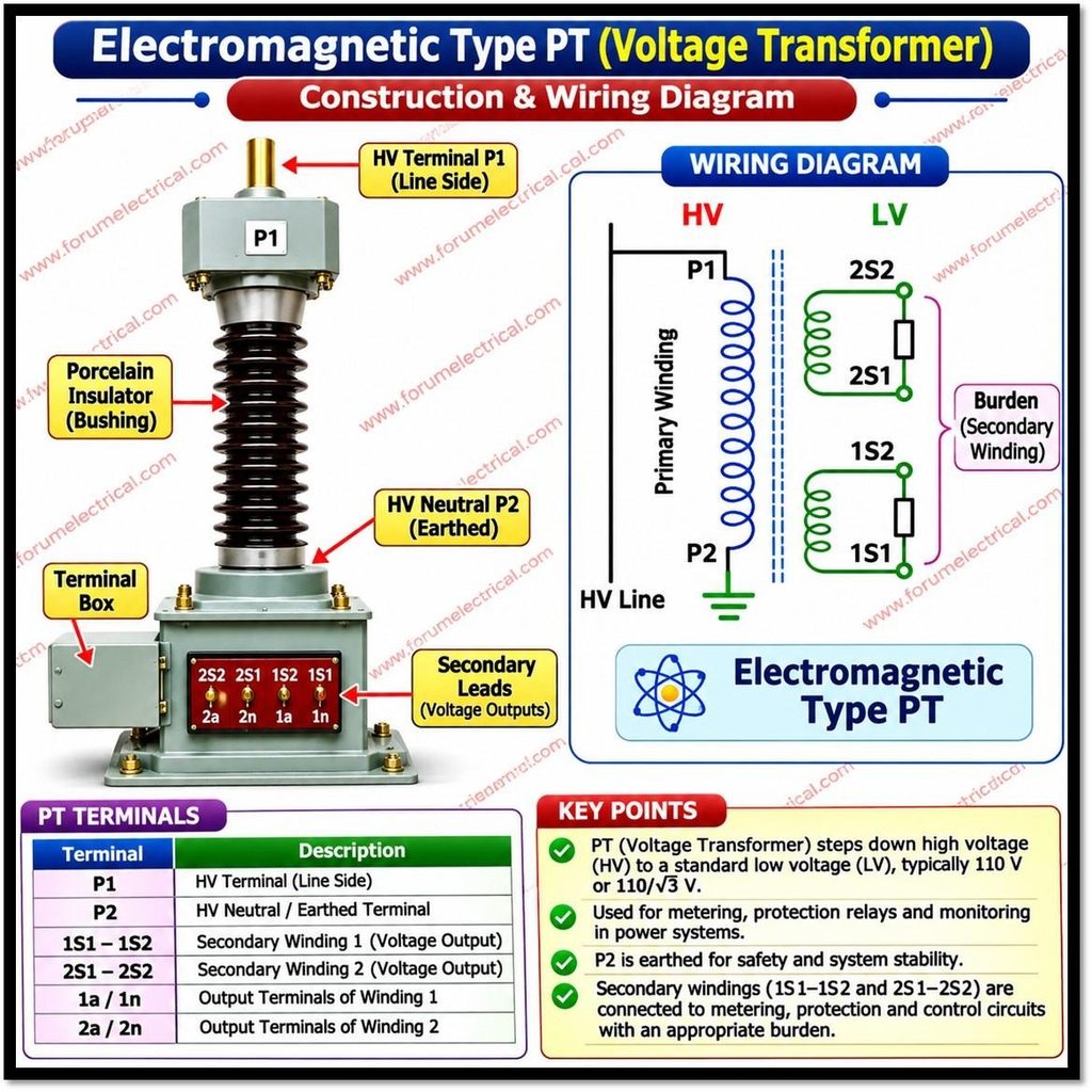
| Terminals & housing | Primary and secondary terminals, enclosure (porcelain (or) composite insulators at higher voltages) and an earthing terminal. |
| Protection devices | HV fuses on the primary side (common at medium voltage) & MCB/fuses on the secondary side. |
Types of Potential Transformers
1). Electromagnetic Potential Transformer
The conventional wound-type PT described above.
It is widely used from low and medium voltages up to roughly 132 kV; beyond that, it becomes bulky & costly because of the insulation required.
2). Capacitor Voltage Transformer (CVT)
A CVT uses a capacitor divider to reduce the line voltage to an intermediate level followed by a smaller electromagnetic transformer to reach the standard secondary value.
It is more economical at extra-high voltages (commonly 132 kV and above) and can also serve as a coupling device for power-line carrier communication.
3). Classification by Construction and Connection
- By phases: Single-phase (phase-to-phase or phase-to-earth) and three-phase PTs.
- By installation: Indoor and outdoor types.
- By insulation: Oil-immersed, cast resin (dry type) & gas-insulated types.
- By purpose: Measuring PTs and protection PTs, or combined-purpose units with separate windings.
Voltage Ratio
The basic relationship is:
PT Ratio = Primary Voltage ÷ Secondary Voltage
Solved Example
11 kV / 110 V PT
Ratio = 11000 V ÷ 110 V = 100 : 1
When the primary voltage is 11000 V, the secondary delivers 110 V.
Conversely, a secondary reading of 105 V corresponds to a primary voltage of 105 x 100 = 10,500 V.
Additional Examples
| PT Rating | Ratio Calculation | Result |
|---|---|---|
| 11 kV / 110 V | 11000 ÷ 110 | 100 : 1 |
| 33 kV / 110 V | 33000 ÷ 110 | 300 : 1 |
| 132 kV / 110 V | 132000 ÷ 110 | 1200 : 1 |
| (11 kV / √3) / (110 V / √3) | 6,351 ÷ 63.5 | ≈ 100 : 1 (the √3 factors cancel) |
Note: the “nominal ratio” (rated primary ÷ rated secondary) is not exactly equal to the actual ratio under load, because of ratio and phase-angle errors.
Main Functions of PT
- Accurate voltage measurement: Supplies voltmeters and transducers with a scaled, proportional voltage.
- Protective relay operation: Provides voltage signals for overvoltage, undervoltage, distance, directional, earth-fault and synchro-check relays.
- Energy metering: Feeds the voltage input of revenue and tariff meters together with CTs.
- Power quality monitoring: Enables monitoring of voltage magnitude, sags, swells, harmonics and unbalance.
- System synchronization: Supplies voltage and phase information for synchronizing generators (or) feeders with the grid.
- SCADA and automation: Provides standardized voltage inputs for remote monitoring and control systems.
- Electrical isolation: Separates HV circuits from low-voltage instruments and personnel.
Why PT is Important?
| Advantages | Explanation |
|---|---|
| Safe voltage levels | Operators and equipment only deal with about 110 V not kilovolts. |
| High measurement accuracy | Defined accuracy classes ensure reliable readings and fair billing. |
| Reliable relay protection | Protection relays receive a faithful reproduction of system voltage during normal and fault conditions. |
| Electrical isolation | Faults or surges on the HV side are kept away from instruments and control panels. |
| Standardized outputs | Common secondary values allow interchangeable meters, relays and control equipment from different manufacturers. |
| Cost reduction | Instruments need only low voltage insulation, so they are smaller & cheaper. |
Accuracy, Errors and Accuracy Classes
Sources of Error
- Ratio (voltage) error: The difference between actual ratio and nominal ratio, caused by winding resistance, leakage reactance and magnetizing current. It is expressed as a percentage.
- Phase-angle (phase displacement) error: The angle by which the secondary voltage phasor (reversed) differs from the primary voltage phasor. It is expressed in minutes / centiradians) and is important for metering and directional relays.
Errors increase when the connected burden exceeds the rated burden and vary with voltage and burden power factor.
Typical Accuracy Classes (IEC 61869-3)
| Purpose | Class | Typical Application |
|---|---|---|
| Measurement | 0.1, 0.2, 0.5, 1.0, 3.0 | 0.1 / 0.2: accuracy and revenue (tariff) metering; 0.5: commercial metering; 1.0 / 3.0: indicating instruments |
| Protection | 3P, 6P | Relaying applications where accuracy over a wide voltage range (including fault conditions) matters |
Accuracy classes for measurement are guaranteed within a specified range of voltage (80% to 120% of rated voltage) and burden (25% to 100% of rated burden at a power factor of 0.8 lagging).
Protection classes are specified over a wider voltage range (from 5% of rated voltage up to the rated voltage factor times rated voltage).
Always confirm these values against the applicable standard edition.
Burden (VA Rating)
Burden is the load connected to the PT secondary, expressed in volt-amperes (VA) at a stated power factor.
The PT must be selected so that the total connected burden does not exceed its rated burden otherwise accuracy is lost.
Indicative Burden Calculation
| Connected Device (illustrative values) | Burden (VA) |
|---|---|
| Voltmeter | 5 |
| Energy meter (voltage circuit) | 5 |
| Protection relay (voltage circuit) | 10 |
| Total (approximate arithmetic sum) | 20 |
A PT with a rated burden of 50 VA, for example, would carry this 20 VA load within its accuracy class.
Actual device burdens vary, so use the manufacturer data.
Standard rated outputs commonly include values such as 10, 15, 25, 30, 50, 75 and 100 VA.
Phasor Diagram of Potential Transformer (PT)
The phasor diagram of a Potential Transformer (PT) illustrates the relationship between primary and secondary voltages, winding impedance drops, excitation current, and phase angle error.
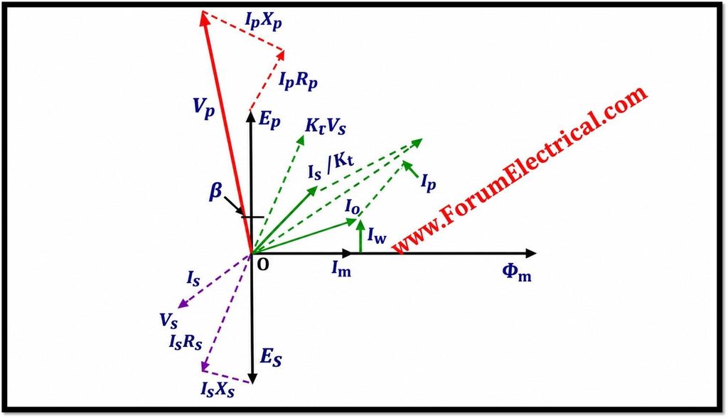
Phasor Diagram Parameters:
- Is – Secondary current
- Es – Secondary induced EMF
- Vs – Secondary terminal voltage
- Rs / Xs – Secondary winding resistance / reactance
- Ip – Primary current
- Ep – Primary induced EMF
- Vp – Primary terminal voltage
- Rp / Xp – Primary winding resistance / reactance
- Kt – Transformation ratio (primary-to-secondary turns ratio)
- Io – Excitation current
- Im – Magnetising component of excitation current
- Iw – Core-loss component of excitation current
- Φm – Main magnetic flux
- β – Phase angle error
The main magnetic flux (Φm) is taken as the reference phasor.
The primary current (Ip) is vector sum of excitation current (Io) and reversed secondary current referred to primary side (Is/Kt).
The applied primary voltage (Vp) supplies the induced EMF (Ep) and compensates for the primary winding resistance and leakage reactance drops (IpRp and jIpXp).
Through mutual electromagnetic induction, the primary induced EMF generates the corresponding secondary induced EMF (Es).
After accounting for secondary winding resistance and leakage reactance drops (IsRs and jIsXs), the resulting secondary terminal voltage is Vs.
The phase angle error (β) represents the angular displacement between the primary and reversed secondary voltage phasors referred to the same transformation ratio.
It is an important accuracy parameter in potential transformer measurement applications.
Typical Applications of Potential Transformer
- Power generation plants.
- Transmission substations.
- Distribution networks.
- Industrial power systems.
- Switchyards.
- Protection and metering panels.
- High-voltage testing laboratories.
In each case, the PT provides the voltage reference required for monitoring, billing, protection and control.
Comparison: Potential Transformer vs Current Transformer
Difference between Potential Transformer and Current Transformer
| Feature | Potential Transformer (PT) | Current Transformer (CT) |
|---|---|---|
| Measures | Voltage | Current |
| Connection to line | In parallel (shunt) with the circuit | In series with the circuit |
| Operating condition | Near no-load | Near short-circuit |
| Secondary standard rating | 110 V (or 110/√3 V) | 1 A or 5 A |
| Secondary must never be | Short-circuited | Open-circuited |
| Primary winding | Many turns, fine conductor | Few turns (sometimes a single bar), heavy conductor |
| Secondary winding | Fewer turns | Many turns |
Installation and Safety Considerations
- Secondary earthing: Connect one point of the secondary winding to earth to prevent the secondary from floating at a dangerous potential if insulation fails.
- Secondary protection: Protect the secondary circuit with fuses or a miniature circuit breaker to guard against secondary short circuits.
- Primary fuses: Medium-voltage PTs commonly have HV fuses on the primary side.
- Short-circuit avoidance: Never short-circuit the PT secondary.
- Polarity: Correct polarity and phase sequence are essential for wattmeters, energy meters and directional or distance relays.
- Voltage factor: Follow standard voltage-factor ratings (for example, 1.2 continuous and 1.5 or 1.9 for 30 seconds, depending on system earthing) so that the PT withstands temporary overvoltages during earth faults.
- Ferroresonance: Follow ferroresonance guidelines for the PT’s connection and loading, particularly in ungrounded or isolated-neutral systems.
Checklist of Potential Transformer (PT)
Always verify the following before selecting (or) installing a PT:
| Parameter | What to Verify |
|---|---|
| Rated primary and secondary voltage | Match the system voltage and the connected instruments (e.g., 11 kV / 110 V). |
| Accuracy class | Choose the class suited to the purpose: metering, protection or both. |
| Burden (VA rating) | Ensure total connected burden stays within the rated burden. |
| Frequency | Rated frequency (50 Hz or 60 Hz) must match the system. |
| Insulation level | Rated insulation (highest system voltage, power-frequency withstand and lightning impulse withstand) must suit the installation. |
| Earthing requirements | Verify system earthing (effectively earthed or not), the primary terminal earthing arrangement and secondary earthing. |
Conclusion
A Potential Transformer steps down high system voltage to a safe, standardized secondary value (commonly 110 V line-to-line or 63.5 V phase-to-neutral) with an accurately proportional ratio.
It is connected in parallel with the circuit, works near no-load, and provides isolation between HV circuits and instruments.
It supports measurement, metering, protection, synchronization, power quality monitoring and SCADA.
Correct selection of voltage rating, accuracy class, burden, frequency, insulation level and earthing is essential for safe and reliable operation.
Example: an 11 kV / 110 V PT has a ratio of 100 : 1.

 is, how it steps down high voltage for safe metering and protection, its working principle, applications and importance in power systems.)