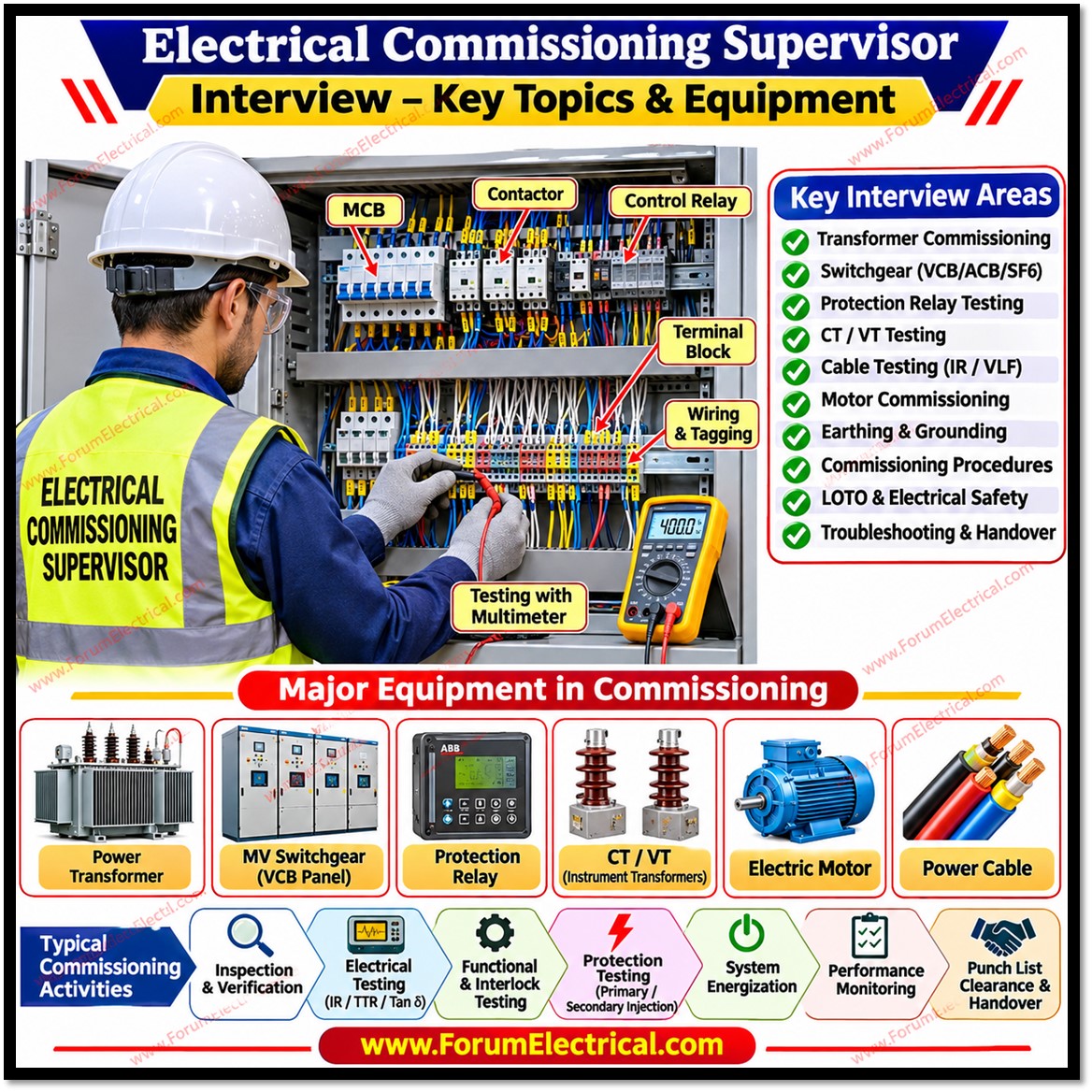
1). What are the main responsibilities of an Electrical Commissioning Supervisor?
The main responsibilities include:
• Supervising electrical installation and commissioning activities.
• Reviewing electrical drawings, single-line diagrams, cable schedules, and technical specifications.
• Ensuring equipment installation complies with approved drawings and applicable standards.
• Conducting pre-commissioning inspections and electrical tests.
• Coordinating with QA/QC, construction, safety, and client teams.
• Verifying protection relay settings and interlock operations.
• Monitoring punch-list clearance.
• Preparing commissioning reports and final handover documents.
2). What is the difference between pre-commissioning and commissioning?
| Pre-Commissioning | Commissioning |
| Pre-commissioning involves inspection, testing, and verification of electrical equipment before energization to confirm that it is correctly installed and ready for operation. | Commissioning involves functional testing, operational verification, protection testing, and energization of equipment to ensure that the complete electrical system operates according to design requirements. |
| Typical pre-commissioning activities include visual inspection, insulation resistance testing, cable continuity testing, and earthing verification. | Commissioning activities include functional testing, protection relay testing, interlock verification, and operational checks. |
3). What documents are required before starting electrical commissioning?
The following documents are generally required:
• Approved Single Line Diagram (SLD).
• Electrical layout and installation drawings.
• Approved cable schedule.
• Equipment datasheets.
• Approved method statements.
• Inspection and Test Plans (ITP).
• Risk Assessment and Job Safety Analysis (JSA).
• Manufacturer’s installation and testing manuals.
• Approved protection relay settings.
• Commissioning checklists and test formats.
• Approved energization procedures.
4). What is an Electrical Single Line Diagram (SLD)? Why is it important?
An SLD is a simplified graphical representation of an electrical power distribution system using single lines and standard electrical symbols. It represents transformers, generators, incoming and outgoing feeders, circuit breakers, isolators, busbars, CTs, VTs, protection relays, and earthing arrangements.
It helps commissioning engineers understand the power distribution arrangement, verify equipment connections, coordinate protection systems, and plan safe energization.
5). What safety precautions should be followed during electrical commissioning?
Important precautions include:
• Follow Lockout/Tagout (LOTO) procedures.
• Obtain the required Permit to Work (PTW).
• Verify isolation of all energy sources.
• Confirm absence of voltage using an approved voltage detector.
• Discharge and earth equipment where required.
• Use appropriate Personal Protective Equipment (PPE).
• Maintain safe approach distances.
• Verify temporary and permanent earthing arrangements.
• Display warning signs and barricade restricted areas.
• Ensure emergency response arrangements are available.
6). What are the important pre-commissioning tests performed on a power transformer?
Common tests include:
• Insulation Resistance (IR) and Polarization Index (PI) tests.
• Transformer Turns Ratio (TTR) test.
• Winding resistance test.
• Vector group verification.
• Magnetic balance and magnetizing current tests.
• Transformer oil BDV and moisture tests.
• Tan Delta and capacitance tests.
• Bushing inspection and testing.
• OLTC functional and operational checks.
• Core and tank earthing verification.
• Protection, alarm, and trip circuit testing.
The applicable tests depend on transformer type, rating, design, and project specifications.
7). What is the Transformer Turns Ratio (TTR) test? Why is it performed?
The TTR test verifies the ratio between the primary and secondary winding turns of a transformer.
Voltage ratio = Primary voltage / Secondary voltage
For a 33/11 kV transformer:
Ratio = 33000 / 11000 = 3
The test helps identify shorted turns, incorrect winding connections, tap changer problems, winding faults, and incorrect vector group or phase displacement. Results should be compared with the manufacturer’s specified values and applicable tolerances.
8). What is the purpose of the transformer winding resistance test?
The winding resistance test measures the DC resistance of transformer windings. It helps identify loose winding connections, poor contact conditions, OLTC contact problems, broken conductors, and abnormal resistance variations between phases.
The test is performed using a winding resistance meter or micro-ohmmeter. Winding temperature and stabilization of readings must be considered when comparing results.
9). What is the purpose of the transformer Tan Delta test?
The Tan Delta test evaluates the dielectric condition of transformer insulation. It can help identify moisture contamination, insulation ageing, oil contamination, and other forms of insulation deterioration.
Tan Delta = Resistive component of current / Capacitive component of current
A higher Tan Delta value generally indicates increased dielectric losses and possible insulation deterioration. Results must be assessed against applicable standards, manufacturer guidance, temperature, and historical test data.
10). What checks are required before energizing a power transformer?
Before energization, verify that:
• All required pre-commissioning tests have satisfactory results.
• Transformer oil level and oil test results meet requirements.
• Buchholz relay and Pressure Relief Device (PRD) are correctly installed and tested.
• Winding and oil temperature indicators are functional.
• Cooling fans and oil pumps operate correctly.
• OLTC operation and indication are verified.
• Differential and REF protection are tested.
• CT polarity and connections are verified.
• Neutral and tank earthing are confirmed.
• Temporary earths are removed under an approved procedure.
• Protection settings and trip circuits are verified.
• Energization approval is obtained.
11). What are the important commissioning tests for a Vacuum Circuit Breaker (VCB)?
Common VCB tests include:
• Insulation resistance test.
• Contact resistance test.
• Open and close operation test.
• Circuit breaker timing test.
• Trip coil and closing coil verification.
• Mechanical and electrical interlock verification.
• Spring charging motor operation.
• Anti-pumping relay operation.
• Vacuum interrupter integrity test using the manufacturer’s recommended method.
• Local and remote operation checks.
12). What is the purpose of the Circuit Breaker Contact Resistance Test?
The contact resistance test measures resistance across the closed contacts of a circuit breaker. It is generally performed using a micro-ohmmeter with a suitable DC test current.
It helps identify poor contact connections, oxidized contacts, contact wear, loose terminals, and abnormal resistance between phases. High contact resistance can cause excessive heating and increase the risk of contact failure.
13). What is the difference between ACB, VCB and SF6 circuit breakers?
Difference between ACB, VCB and SF6 circuit breakers:
| ACB (Air Circuit Breaker) | VCB (Vacuum Circuit Breaker | SF6 Circuit Breaker |
| ACB (Air Circuit Breaker) uses air as the arc-extinguishing medium and is commonly used in low-voltage systems. | VCB (Vacuum Circuit Breaker) uses a vacuum interrupter and is commonly used in medium-voltage systems. | SF6 Circuit Breaker uses sulphur hexafluoride gas as the insulating and arc-extinguishing medium and is used in medium- and high-voltage applications. |
Selection depends on voltage level, fault current, application, environmental considerations, and manufacturer design.
14). What is the purpose of protection relay testing during commissioning?
Protection relay testing verifies that a relay detects abnormal electrical conditions and operates the appropriate circuit breaker within the specified time.
Common tests include secondary injection, primary injection where required, overcurrent, earth-fault, differential, under-voltage, over-voltage, and frequency protection tests. Trip circuits, alarms, annunciation, and relay communication or SCADA signals should also be verified.
15). What is the difference between primary injection and secondary injection testing?
The difference between primary injection and secondary injection testing are:
| Primary Injection Testing | Secondary Injection Testing |
| Primary injection testing introduces test current into the primary circuit. | Secondary injection testing introduces test signals directly into the relay secondary inputs. |
| Depending on the test arrangement, it verifies the CT and associated secondary current path, relay input, and protection operation. It generally requires higher test current. | It verifies relay pickup, timing, logic, and associated functions, but does not by itself prove the complete primary CT circuit. |
16). What tests are performed on Power Cables before Commissioning?
Common cable tests and checks include:
• Visual inspection and route verification.
• Cable identification.
• Conductor continuity test.
• Insulation resistance test.
• Phase identification test.
• Sheath integrity test, where applicable.
• High-voltage withstand testing as specified.
• Cable termination inspection.
• Earthing and bonding verification.
For medium-voltage cables, VLF or another approved withstand-testing method may be specified depending on cable type and project requirements.
17). What is the purpose of the Insulation Resistance (IR) test?
The IR test measures the resistance of electrical insulation between conductors and between conductors and earth. It is performed using an insulation resistance tester.
It helps identify moisture ingress, insulation deterioration, contamination, cable insulation damage, and winding insulation defects. The acceptable value depends on equipment voltage, temperature, insulation type, manufacturer recommendations, and applicable standards.
18). What are the important commissioning tests for an electrical motor?
Common motor commissioning checks include:
• Insulation resistance test.
• Polarization Index test, where applicable.
• Winding resistance measurement.
• Phase sequence verification.
• Protective earth continuity test.
• Alignment verification.
• Bearing and lubrication inspection.
• No-load running test.
• Direction of rotation test.
• Vibration measurement.
• Temperature monitoring.
• Load test, where specified.
During operation, check for abnormal noise, vibration, overheating, and current imbalance.
19). How do you verify the earthing system during electrical commissioning?
Earthing verification includes:
• Earth electrode resistance measurement.
• Protective conductor continuity testing.
• Equipment body earthing verification.
• Transformer neutral earthing verification.
• Cable tray and cable armour bonding checks.
• Earth grid continuity testing.
• Earth conductor size and connection inspection.
• Touch and step voltage assessment, where required.
Results must comply with project specifications and applicable earthing standards.
20). What is the difference between earth resistance and earth continuity testing?
The difference between earth resistance and earth continuity testing are:
| Earth Resistance Testing | Earth Continuity Testing |
| Earth resistance testing measures the resistance of an earth electrode or grounding system with respect to the general mass of earth. It is generally performed using an earth resistance tester. | Earth continuity testing verifies the electrical continuity of protective conductors and bonding connections. It is generally performed using a low-resistance ohmmeter. |
| Earth resistance evaluates the electrode or grounding system performance. | Earth continuity testing identifies open circuits or poor bonding connections. |
21). What is an interlock system? Why is it important in electrical switchgear?
An interlock system prevents unsafe or incorrect switching operations. Common types include mechanical interlocks, electrical interlocks, and key interlocks.
For example, depending on the switchgear design, an interlock may prevent operation of an isolator under load or prevent closing an earthing switch while the associated circuit is energized. Interlocks improve personnel safety and help prevent equipment damage.
22). What is the purpose of CT polarity testing during commissioning?
CT polarity testing verifies the relationship between the primary and secondary current directions. Correct polarity is essential for differential protection, Restricted Earth Fault (REF) protection, directional overcurrent protection, metering, and power measurement.
Incorrect CT polarity can cause protection maloperation, particularly in differential protection schemes.
23). What is a punch list in electrical commissioning?
A punch list records outstanding installation, inspection, testing, or commissioning issues that must be resolved before the relevant system acceptance or handover milestone.
Typical items include incomplete cable termination, missing equipment labels, incorrect cable tagging, incomplete earthing connections, failed insulation resistance tests, incorrect relay settings, and missing test certificates. Items are prioritized and cleared according to project requirements.
24). What is the role of an Electrical Commissioning Supervisor during system energization?
The supervisor ensures that technical and safety requirements are fulfilled before, during, and after energization. Responsibilities include:
• Confirming completion and acceptance of commissioning tests.
• Verifying approved energization procedures.
• Coordinating with the operations team.
• Confirming PTW closure and authorized release.
• Verifying removal of temporary earths.
• Confirming protection relay availability.
• Checking breaker and isolator positions.
• Ensuring personnel are clear of the equipment.
• Coordinating switching operations with authorized personnel.
• Monitoring electrical parameters after energization.
• Recording observations and commissioning results.
Energization must be performed only under the authority of designated switching or operating personnel.
25). How do you handle an Electrical Equipment Failure during Commissioning?
Follow a systematic troubleshooting process:
1. Stop the commissioning activity and make the equipment safe.
2. Isolate the equipment and implement LOTO procedures.
3. Review test results, drawings, and manufacturer specifications.
4. Identify the root cause using suitable diagnostic tests.
5. Coordinate with engineering, QA/QC, and maintenance teams.
6. Rectify the fault using an approved procedure.
7. Repeat the required inspection and commissioning tests.
8. Document the failure, corrective action, and final test results.
Release the equipment for commissioning only after the fault has been resolved and the acceptance criteria have been met.

