
Protection system testing is essential for ensuring that electrical systems are reliable and safe. It starts with an overview of protective systems and their function in preventing equipment damage & ensuring operational continuity.
The testing process employs a variety of methodologies and processes, including primary & secondary injection testing, as well as accurate step-by-step procedures.
During testing, it is important to identify and resolve frequent issues via effective troubleshooting.
Following recommended procedures along with safety considerations is essential for ensuring that tests are carried out properly and in accordance with industry norms and regulations.
Purpose
It is necessary to verify some protection systems, such as differential and distance protection working correctly and in the manner that was needed of them.
These tests were required to be carried out both before and following the commissioning process.
Equipment Required
- Multimeter
- Clamp meter
- Primary injection test kit
- Secondary injection test kit
Test Procedure
Stability Test
In order to illustrate the stability of the unit protection against through faults and the sensitivity of the unit protection against internal faults, the stability & sensitivity test would be carried out.
Following is an explanation of the test’s fundamental principle.
Because of the location of the CTs, the protected zone of the unit protection comes with several limitations. During the stability test, the primary current will be injected via one set of two CTs in such a way that one of the currents will be directed inwards and the other will be directed outwards.
In order to ensure that the connection is made correctly, the relay terminal must not have any operational current observed.
A sensitivity test is required to be carried out using the same set-up, but with either the CT polarity going in the other direction or injecting primary current on only one of the CTs in the set.
To ensure that the relay is functioning correctly, the operational current must be monitored at the relay terminal.
Busbar Differential Protection
Sensitivity Test
It is required that the test connection be made in the manner shown in diagram 1.
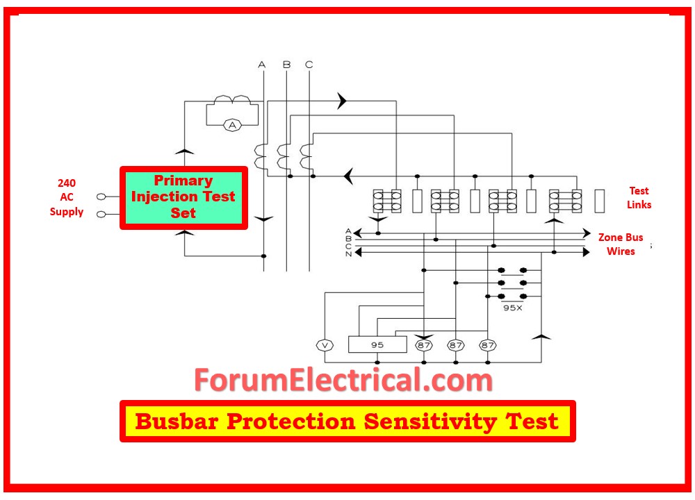
High impedance differential relays are able to make use of this. Under the condition that all CTs are connected to the zone, it is necessary to measure the minimum primary operational current.
To activate the relay, inject primary current and gradually increase it until it is fully operational.
In accordance with the test form, each and every measurement must be carried out.
The procedure must be carried out with one set of CTs injected and one set of CTs secondary reversed in the event that bias differential protection is required.
Stability Test
It is required that the test connection be made in the manner seen in diagram 2.
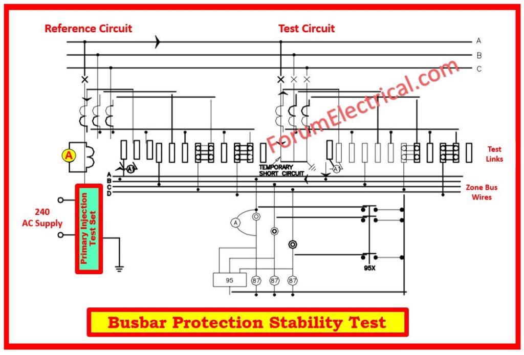
Apply a primary current that is at least fifty percent (50%) of the primary operational energy.
In order to assess the CTs secondary current and differential current at the relay, measurements are required.
An accurate measurement of the differential current must be zero in order to be considered acceptable.
Transformer Differential Protection
Stability Test
Diagram 3 and 4 are the diagrams that should be used to complete the test connection.
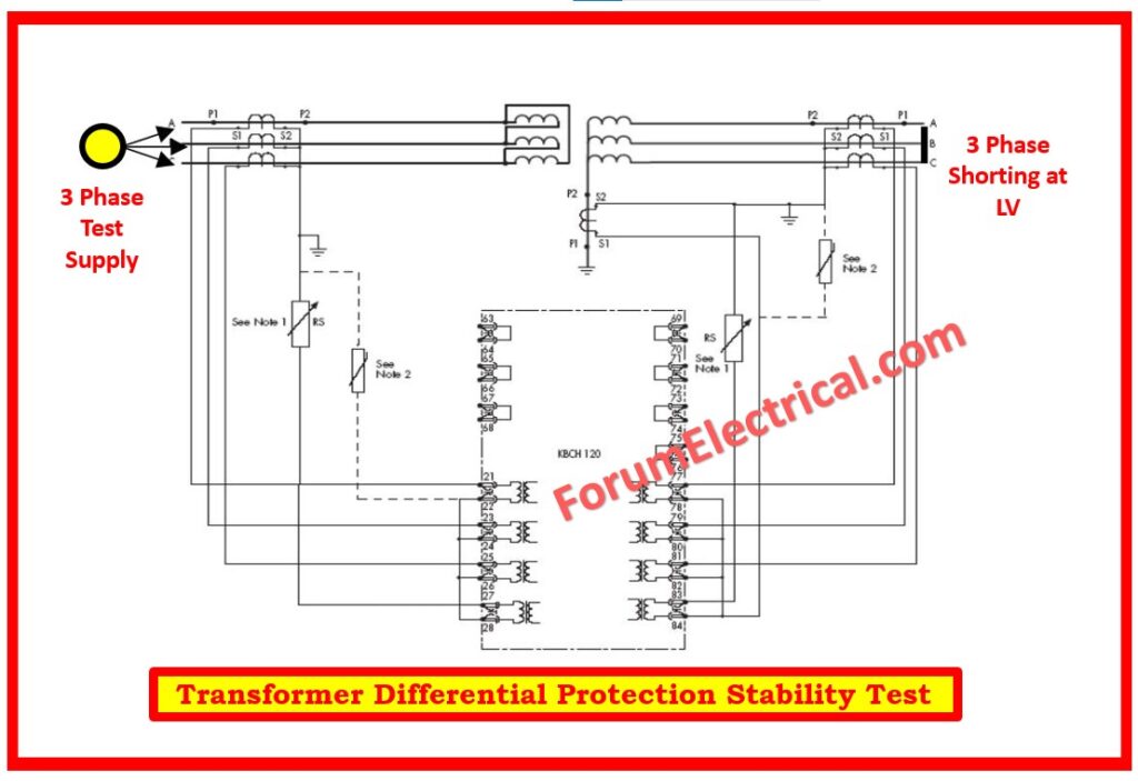
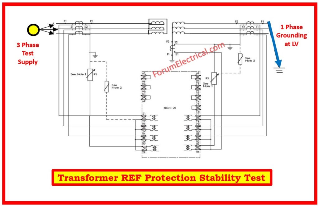
Immediately following the CT with a nominal tap, the test voltage is to be injected into one winding, and another winding is to be shorted.
It is important to take note that the test voltage is injected prior to the differential CT.
Measurements are going to be taken of the CT’s secondary current.
The only current that will be recorded at the relay is the through current, and differential current will not be observed in order to ensure that the connection is made correctly.
For both the minimum and maximum tap, the test described above must be carried out.
An extremely minute differential current will be recorded throughout the course of this test.
The identical set-up will be used for the sensitivity test, and one of the side CT secondary rotations will be reversed in each phase.
Pilot Wire Protection End-To-End Test
The purpose of this test is to verify that the pilot wire protection is correctly linked with the remote end and ensure that the operation is carried out as intended with a single end feed.
Please ensure that this test is carried out in accordance with the manufacturer’s instructions and that the limitations have been followed.