
The disconnectors are electrical application devices. These are devices which are employed in the interruption of circuits for safety.
- What is a Disconnector Switch?
- Types of Disconnector Switch
- Test Procedure
- Purpose
- Testing Instruments Required
- Mechanical and Visual Inspection
- Insulation Resistance Test
- Contact Resistance Test
- High Voltage Test
- Applicable Standard
- Advantages of Disconnector Switch
- Application of Disconnector Switch
- Why are Disconnector Switches applied?
Thus, if you would like to learn more about the disconnector switch as one of the popular types of disconnectors applied to various electrical circuits, this post will be informative for you.
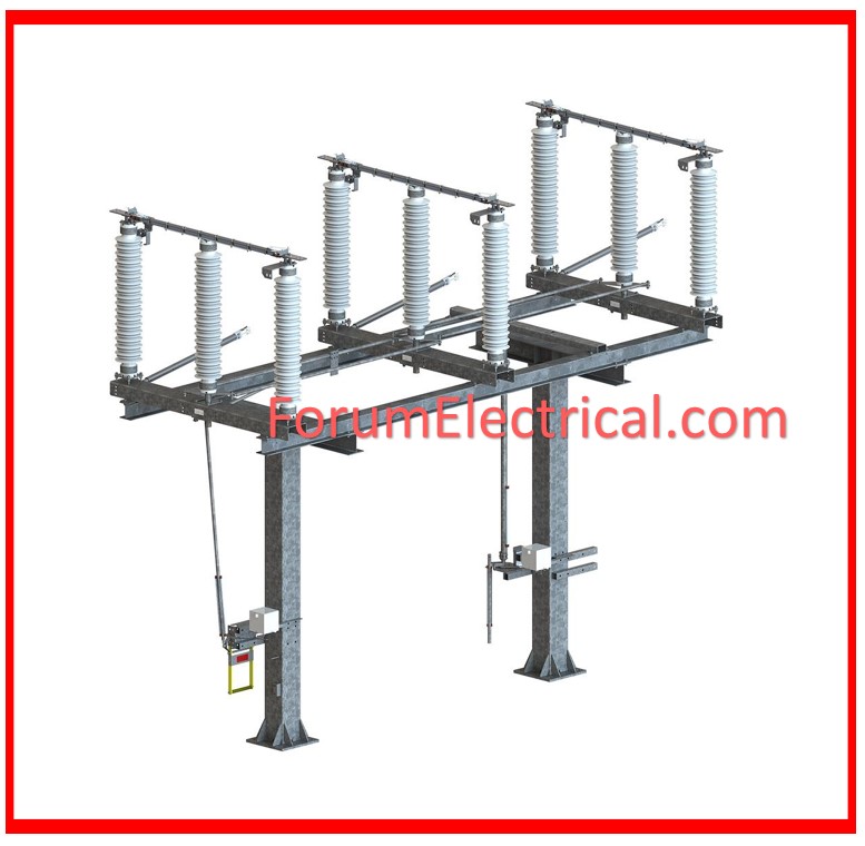
What is a Disconnector Switch?
Disconnector Switch is also known as a switch disconnector.
A disconnector switch is another electrical device that performs the same work as a disconnector.
As mentioned earlier, a disconnector is always designed to open or interrupt the electrical current flow for safety purposes only.
Ex: Whenever electrical equipment is undergoing repair and or maintenance, the electrical flow in the equipment has to be interrupted for safety.
For this reason, the main and foremost function of a switch disconnector is to interrupt the electric supply to all the appliances that are connected in an electrical circuit.
As you are aware, electricity is dangerous, or rather deadly when operated without precautions; switching off the power allows you to operate any electrical equipment safely for repair and other associated purposes.
The disconnector switch will interrupt the power current to the equipment from the input section, or at the output section.
Types of Disconnector Switch
The Disconnector switches are also of many types; some are manually operated and others automatically operated.
As a result, mechanical disconnectors are prominent; there are also automatic disconnectors.
However, one has to note that the usage of these two disconnector switches differ depending on the disconnector.
As we understand, the disconnector switch acts as a disconnector in addition to acting as load switch. In any case, they are always replaceable to afford the qualities of an electrical isolator and a load switch.
This makes the Disconnector switch very popular today in electrical circuit networks.
Test Procedure
Purpose
To verify the physical and electrical condition of the disconnector/ground switch.
Testing Instruments Required
- Insulation Tester
- Micro ohmmeter and high-voltage test kit.
Mechanical and Visual Inspection
- Inspect for any physical damage or faults.
- Ensure that the information on the nameplate is correct.
- Verify the tightness of all bolted connections.
- Check for the smooth operation.
- Check that the earth switch is linked to the earth bar.
- Check all mechanical interlocks.
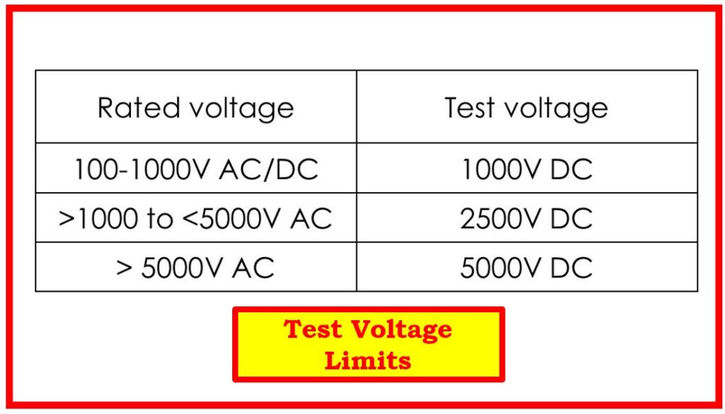
Insulation Resistance Test
- The test voltage must be between phase to earth and across poles.
- Each phase leads to Earth (or) body.
- Across the pole for each phase.
- The applied test voltage limits must be as per table.
Contact Resistance Test
- This test confirms the resistance of the primary contacts.
- Inject 100A DC current into the main contact while keeping the disconnector/earth switch closed.
- We measure the voltage drop across the contact and calculate the resistance.
- In many instruments, resistance can be measured directly.
Limits: Values should be compared to factory test reports or manufacturer’s claimed values for reference.
High Voltage Test
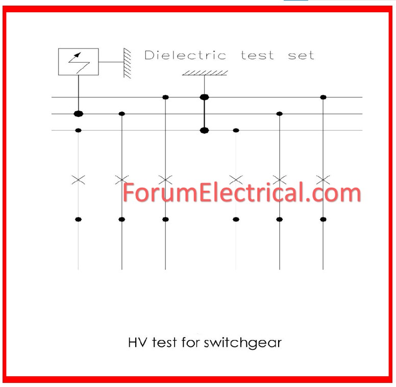
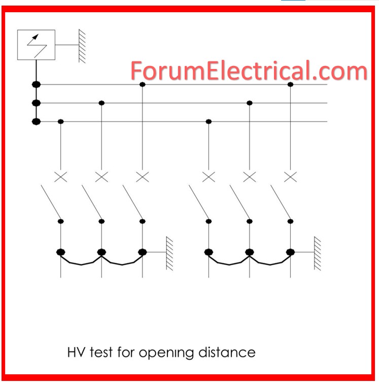
- The high voltage test normally involves passing through a high voltage, several times the ratings or normal voltage across the open contacts or between live parts and earth.
- Ensure that the dielectric strength of the insulation is as required.
- Verify that the disconnector switch will be capable of providing isolation for electrical circuits during high voltage.
The test is often carried out during the last stages of the final acceptance tests before the switch is made operational.
Applicable Standard
IEC 60265: HV switches 1-66 KV.
Advantages of Disconnector Switch
It is perfect and reliable in switching electrical devices off and on, and is also functional in breaking and connecting electrical circuits.
Application of Disconnector Switch
- They comprise fuse switch disconnecting devices, normal disconnecting devices as well as popular circuit breaking devices.
- However, these Disconnector switches are specially formed to be effective on different operations, but they have a common purpose is to disconnect electricity.
- . Their main use in the substations is function to isolate large powers in transmission lines and transformers for safety operating.
For this reason, you will always find all these types of disconnectors used together in different electrical circuits.
Why are Disconnector Switches applied?
A switch disconnector, or an isolating switch or disconnector switch serves primarily to disconnect power supply from electrical equipment connected to a circuit for safety purposes during operations such as maintenance.
These disconnectors also interrupt the electrical circuits in a large electrical distribution.
For this reason, they are applied on many industrial applications, manual as well as motor operated disconnectors.
Further, the disconnectors with high voltage ratings are always fitted in the higher voltage electrical substations
The disconnectors in particular are always safe and efficient in disconnecting the large power and therefore most often used for disconnecting the larger electrical distribution circuits and the sub stations. Nevertheless, the electrical disconnectors are without provisions to handle circuits; they are safe only in their probability of interrupting the power flow through the transmission line.