A PLC is a microprocessor-based digital electronic device that stores user-defined instructions in programmable non-volatile memory and performs specific control functions such as
- Inputs & Outputs in PLC
- Analog Inputs for PLCs
- Analog Inputs’ Functions in PLC
- Thermocouple Sensors
- RTDs (or) Resistance Temperature Detectors
- Displacement Sensors
- Analog PLC Outputs
- Digital Inputs
- Digital Inputs’ Functions in PLCs
- Start / Stop Push Buttons in PLC Control Panel
- Proximity Sensors
- PLC Systems – Limit Switches
- Thermostats
- Level Sensors
- Digital PLC Outputs
- Programming logic,
- Sequencing,
- Timing,
- Counting, and
- Arithmetic operations
to control various electromechanical systems and industrial processes.
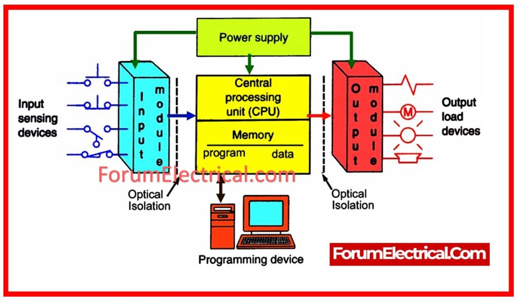
As a user, you can program a PLC with a programming device such as a (HHM) – Hand-Held Monitor (or) a desktop computer connected to the PLC via LAN connection.
PLCs are now widely regarded as the foundation of industrial automation around the globe.
A PLC controller, like any other electrical device, requires input before producing output.
However, the operation of a PLC system is not quite as simple as stated. The PLC system must be supplied with advanced electronic Input & Output (I/O) modules in order to regulate a process or machinery.
These I/O modules connect the PLC CPU to the actual globe, specifically the field input/output devices.
The input modules collect data from all field input devices and send it to the (CPU) PLC processor as voltage (or) current signals. The received signals serve as PLC inputs.
The CPU then converts the received information into pre-coded data, which it utilizes, together with the executed results of its programmed logic, to operate the field output devices through the Output module.
Thus, PLC outputs are the proper control commands that PLC CPU sends out to manage/operate physical devices after running the user program from (RAM) – Random-Access Memory.
Inputs & Outputs in PLC
Every PLC is required to read signals from sensors such as switches and encoders, as well as manage real-world devices such as
- Solenoids,
- Valves, and
- Motors.
This enables the PLC to respond to its surroundings and control numerous physical processes appropriately. This is usually referred as input/output (I/O).
PLC inputs are made up of input modules that collect data from field input devices and transfer it as voltage (or) current signals to the (CPU) PLC processor.
The CPU subsequently processes this information with preprogrammed instructions. It uses output modules to the control field output devices according to the results of its programmed logic.
Thus, PLC outputs are the instructions supplied by the CPU to control real-world devices based on the user’s program stored in RAM.
They instruct the devices based on the program’s commands.

Analog Inputs for PLCs
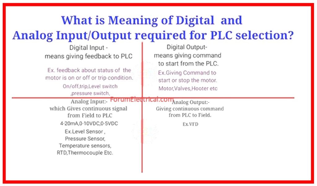
Continuous signals from field input devices are sent to the PLC CPU via analog input modules as analog PLC inputs.
More accurate measurements are possible because these signals span a larger range of values than straightforward binary inputs.
Ex:12-bit and 13-bit analog input signals that a PLC receives can indicate a wide range of values.
To ensure efficient monitoring & control of industrial operations, analog input modules in PLC systems measure voltages & currents within specified ranges such as 0-20 mA, 4-20 mA, 1-5 VDC, & 0-10 VDC.
Analog Inputs’ Functions in PLC
Thermocouple Sensors
Temperature sensors called thermocouples are used in many different applications to identify temperature changes.
Thermocouple wires are made comprised of two different metal wires that are linked at one end to create a hot junction that measures temperature.
A thermoelectric voltage is produced in response to temperature changes at the hot junction, and this voltage is directly proportional to the temperature changes being recorded.
Usually, these thermoelectric voltage signals fall into the millivolt (mV) region and are modest analog signals.
Properly set thermocouples provide significant measurements of temperature capabilities across a wide range of values, despite their minute magnitude.
Because of their accuracy, resilience, and fast reaction times, thermocouple sensors which are utilized in PLC control systems that are dependable tools for measuring temperature.
RTDs (or) Resistance Temperature Detectors
Passive temperature sensors called Resistance Temperature Detectors (RTDs) alter resistance in reaction to variations in temperature.
RTDs require an external excitation current in order to operate, in contrast to active sensors, which provide their own outputs.
Therefore, in order to measure the resistance of the resistive element in the RTD, they require external electronic devices.
This measured resistance is subsequently converted to temperature by the external electronic equipment.
Accurate temperature measurement is made possible by the RTD sensor’s resistance, which changes proportionately with temperature.
RTDs are a popular option for a variety of temperature monitoring applications because they are more accurate, stable, and robust than thermocouple sensors.
RTDs are frequently used in analog PLC inputs for accurate temperature measurement in industrial settings.
Displacement Sensors
Displacement sensors, sometimes referred to as position sensors, gauge an object’s location and the separation between it and a predetermined reference point.
These devices serve as analog field inputs and provide a set of displacement values to the analog PLC input modules in industrial settings where accuracy is essential.
The following are examples of common displacement sensor types.
Rotary & Linear Potentiometers: These potentiometers use the Ohm’s Law principle to show changes in the displacement of the target item.
Changes in the target object’s distance are reflected in variations in the output voltage.
PLC systems use rotary potentiometers to measure angular distance, which is perfect for things that rotate.
In contrast, the displacement of items traveling in a straight line is measured using linear potentiometers.
LVDT: The rectilinear motion of a connected mechanical target object is converted into an electrical signal using linear variable differential transformers (LVDTs), which function as electromechanical transducers.
These parts are necessary for PLC-controlled systems that need a constant AC voltage in order to show distance changes in a straight line.

Analog PLC Outputs
Analog PLC outputs provide accurate control over a range of industrial processes by sending continuous signals from PLC CPU to the field output devices.
Usually, these outputs offer voltage or current signals that allow system parameters to be adjusted.
To supply voltage or current signals within preset ranges, such as ±5 V, ±10 V, 0–5 V, 0–10 V, 0–20 mA, (or) 4–20 mA, the majority of PLC systems use analog output modules.
In industrial environments, field device control and operation depend heavily on analog PLC outputs.
They can be used, for instance, to provide a speed reference signal to the VFD in order to precisely control motor speed.
Similar to this, in circumstances when pressure measurement is essential, an analog pressure meter may be connected as a field output device to show pressure measurements and provide real-time piping system monitoring.
- Temperature monitoring,
- Water level management, and
- Machinery & equipment control
are all made possible by analog PLC outputs.
Ex: A 4–20 mA analog PLC output can be used to run a temperature gauge that measures temperatures between -20°F (-28.89°C) and 200°F (-93.33°C).
Similarly, an analog PLC output that functions between 0 and 5V DC can be used to control the power output of an electric generator at any point across 0 & 2000 kW (Kilo-Watts).
This adaptability shows how many different field equipment in industrial settings can use analog PLC outputs.
Digital Inputs
Field devices that are ON or OFF send signals to discrete or digital PLC inputs.
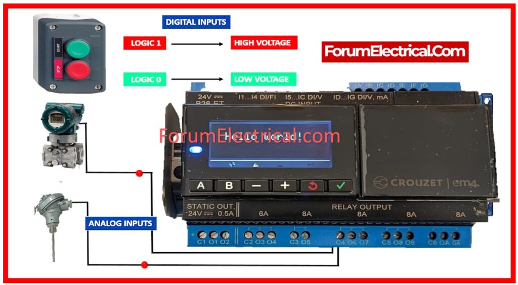
These signals are based on the binary system, where a HIGH state is represented by 1 and a LOW state by 0. In PLCs that normally run on 24 VDC, a HIGH signal is recorded whenever the output voltage from the linked device hits 24 VDC, even though it is represented by 1.
These binary inputs are used by the PLC system to distinguish between the OFF and ON states of field devices.
Digital Inputs’ Functions in PLCs
Field devices send digital input signals to digital input modules, which then forward them to PLC system.

These devices are vital for giving the PLC the necessary input data for processing & control.
The PLC system receives digital input signals from digital field input devices using digital input modules.
You’ll probably encounter the following digital field input devices in practically every PLC application:
Start / Stop Push Buttons in PLC Control Panel
- Normally Closed (NC) and
- Normally Open (NO).
Proximity Sensors
In PLC systems, proximity sensors are essential parts.
Without making physical contact, they use changes in electromagnetic radiation (or) fields to determine whether or not adjacent objects are there as well.
Depending on the material characteristics of the items they detect, different kinds of proximity sensors are employed.
Ex: Capacitive sensors are excellent at recognizing plastic targets, whereas inductive sensors are best at detecting metal things.
Proximity sensors function similarly to switches and offer binary outputs.
Ex: A photoelectric sensor changes from an OFF to an ON state when it receives infrared light.
These sensors typically include receivers such as photodiodes or phototransistors and an LED that emits infrared light.
Common digital input devices, PNP and NPN proximity sensors provide PLC systems with either HIGH (or) low-voltage signals.
When a PNP sensor detects an object, it sends a HIGH signal; when it doesn’t, it sends a LOW signal.
On the other end, NPN sensors detect objects with a LOW output and change to a HIGH output as the thing goes away.

PLC Systems – Limit Switches
Limit switches, which alter their status when predetermined limits are reached, are essential parts of PLC systems.
In automated settings, the signal process stops, providing flexibility in restricting various physical elements.
This emphasizes how crucial they are to PLC operations as digital inputs.
The following limit switch types are frequently seen in PLC applications.
Thermostats
Thermostat also referred to as temperature limit switches, thermostats track temperature variations in PLC-controlled systems & signal when predetermined temperature thresholds are reached.
They serve as digital inputs for PLCs and are available in 2 varieties: normally closed (NC) and normally open (NO), depending on the particular industrial requirements.
Level Sensors
Level limit switches, also known as level sensors, are essential components of PLC systems that monitor liquid levels in conjunction with valves.
They are essential for preserving the levels of liquid in tanks.
They ensure accurate
- Liquid level monitoring and management,
- Improving operational effectiveness and
- Safety in industrial environments.
Digital PLC Outputs
Accurate and automated operation of machinery in factories as well as other locations is made possible by digital PLC outputs, which link the PLC brain with the real-world devices.
In order to determine the operational condition of linked devices, these control circuits use binary data, sending processed signals in 1s & 0s.
By using an ON/OFF control scheme, digital PLC outputs make it easier to manage a variety of processes and provide field equipment control that is dependable and easy to use.
They enable the PLC to effectively control field equipment by carrying out commands via binary signals, improving operational effectiveness and guaranteeing peak performance in industrial settings.
Because digital PLC outputs offer flexible control over a variety of field output devices, they improve automation & efficiency in industrial processes.
These devices consist of:

Indicator Lights: Digital PLC outputs can easily control indicator lights, such as pilot lights or light bulbs.
They provide clear visual feedback on the state of the system or machine.
A red pilot light could indicate a system failure explaining the purpose of digital field output devices in the PLCs.
Alarms: Level switches, which act in combination with valves to control tank liquid levels, are essential components of PLC systems.
They provide accurate liquid level monitoring and control, which is consistent with the function of the digital inputs in PLCs to support safe and effective industrial operations.
Actuators: Actuators are essential for carrying out instructions from PLCs because they transform electrical impulses into mechanical motion.
Actuators convert digital output signals into useful actions, whether they are producing linear or rotary movement.
This allows for precise control over a variety of processes in industrial settings.
Solenoid Valves: Solenoid valves have important functions for fluid management in PLC systems because they regulate the flow of gases or liquids.
To manage the fluid flow, these electrically operated valves open or close.
Digital field output devices in PLCs are primarily used to activate the solenoid and adjust the valve, ensuring smooth system functioning.


