Transformer is an electrical device which employs the working of Faraday’s law of induction with the help of which Faradays described that the magnitude of an EMF produced inside a conductor is due to electromagnetic induction.
- What is meant by the term On-Load Tap Changing Transformer (or) OLTC?
- Tapping Location
- Construction of OLTC
- On-Load Tap Changing Transformer (OLTC) using a Reactor
- On Load Tap Changing Transformer (OLTC) using a Resistor
- Advantages of OLTC
- Disadvantages of OLTC
- Applications of OLTC
- What is the tap range of OLTC?
- What is the IEC standard for On-Load Tap Changer?
- What is No Load Tap Changing Transformer (or) NLTC?
- Significance of OLTC in Power Systems
A transformer includes two varieties of windings such as primary and secondary. Its main purpose is to switch on electrical energy from one circuit to another circuit.
When a voltage is supplied then it should be regulated properly. Therefore, to preserve the capacity of the voltage supply by the transformer, we employ the tapping technique.
When the number of turns in a transformer can be made adjustable through tap changing mechanism using taps in different points of transformer tapped to either primary or secondary winding.
This mechanism can be done in two ways:
- NLTC (No-Load Tap Changing Transformer) and
- OLTC (On-Load Tap Changing Transformer).
This post gives a briefing about OLTC.
What is meant by the term On-Load Tap Changing Transformer (or) OLTC?
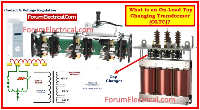
An On-Load Tap Changing Transformer (OLTC) refers to an open load tap changer and is also called an on-circuit tap changer (OCTC). They should be applied in regions where there is a problem with tapping chiefly because of an unsatisfactory tap change.

The number of times can be manipulated but without the destruction of the circuit in the process.
It has 33 taps out of which
- 1 Tap – Center rated tab and
- 16 Taps – Increases the ratio of windings & remaining
- 16 Taps – Decreases the ratio of windings.
Tapping Location
Tapping is done at the ending of phase, or at the winding center or at a point of neutrality.
By positioning them at different points, it offers a number of advantages, including the following:
- It is possible to reduce the amount of insulators needed for the bushing if the tap is connected at end of the phase.
- There will be a decrease in the amount of insulation that exists between the various components if the tap is connected at middle of the winding.
This type of arrangement is required in large transformers.
Construction of OLTC
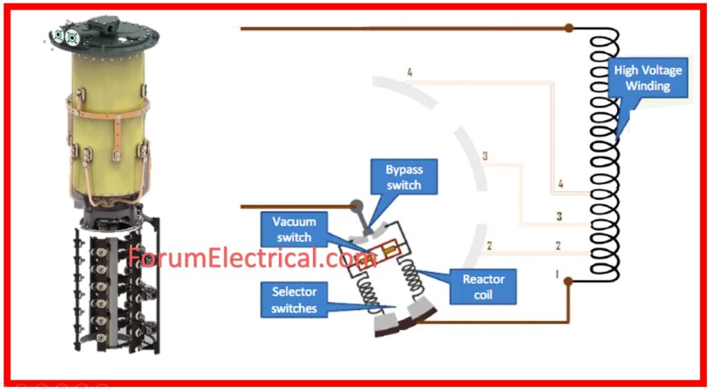
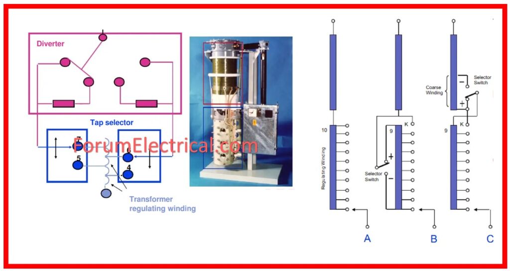
Among its components are a center tap (Reactor-or-Resistor), voltage V1 employees, high voltage (HV) winding and low voltage (LV) winding switch s, and a diverter switch. Additionally, there are four selector switches involved S1, S2, S3, S4 & Tap T1, T2, T3, T4.
Taps are located in a different section where you can find the OLTC switch located.
This tap changer operates remotely as well as operation by a small switch for safety reasons.

Unconventional design feature has the provision of a separate handle for manual control.
When the selector switch malfunctions, they cause a short circuit, and this is catastrophic to the transformer.
Hence to overcome the above, we incorporate resistor/reactor in the circuit which creates impedance thus minimizing on short circuit.

On-Load Tap Changing Transformer (OLTC) using a Reactor
If the diverter switch is closed and selector switch1 is closed the transformer goes into operation. Now if we want to change the selector switch from 1 to 2 then this can be done with the help of tap as follows.
Steps for Operation of OLTC
Step-1: Firstly turn on the diverter switch, which implies no current passes through selector switches
Step-2: Connect tap changer to selector switch number two
Step-3: Open the selector switch 1
Step-4: The state in which current is in the transformer: Close the diverter switch.
Step-5: It is called reactance control, only half a portion is connected for limiting the current while the tap is being adjusted.
Step-6: The secondary output voltage can be varied in either high or low voltage by utilizing the selector switch then the diverter switch on the number of turns ratio.
Because of its larger power system application, it is required to adjust the transformer taps several times to achieve the necessary voltage is on the system based on load requirements.
In other terms, the demands for its continuance does not allow the transformer to disconnect the supply.
Therefore in order to avail the continuous supply, an on-load tap changer is used.

On Load Tap Changing Transformer (OLTC) using a Resistor
The operation of the on-load tap changing transformer using a resistor is described as follows:
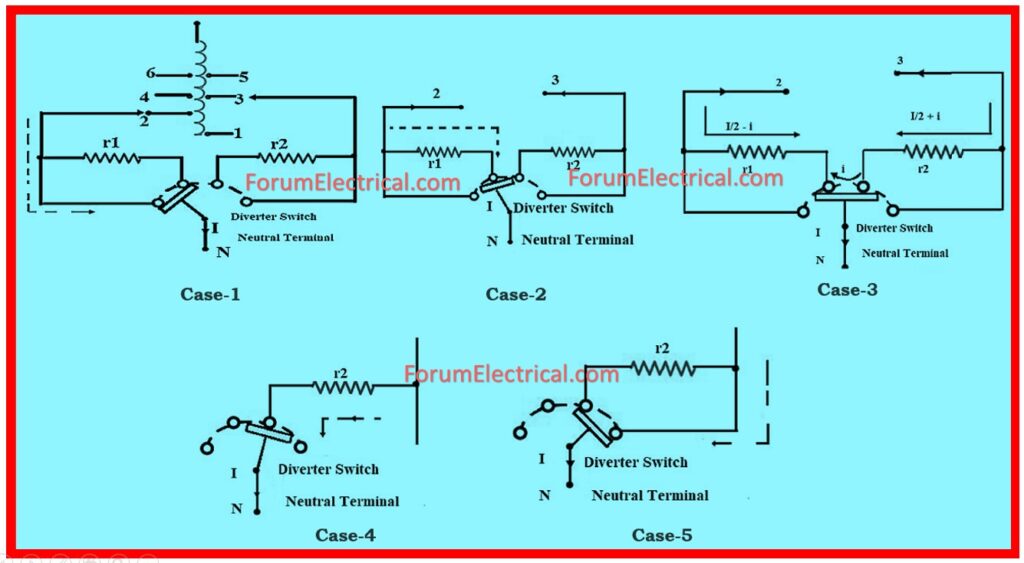
It as comprising one resistor r1 & r2 and four taps t1, t2, t3, t4.
Depending on the position of the taps the switches are connected and currents which are indicated in the following case are carried out.
Case-1: In the case of diverter switch is connected at tap1 and tap2, the load current from top to tap1 as illustrated.
Case-2: If the diverter switch is connected at tap2 the load current flows from r1 to tap.
Case-3: If the diverter switch is linked between tap2 and tap3, current distractions, which is represented by (I/2 – i) from r1 and (I/2 +i) from r2 as shown.
Case-4: If the diverter switch is provided interconnection between tap3 and r2, then the current will be passed through r2 to tap.
Case-5: If the diverter switch is connected at tap3 the current I is shorted as depicted.

The basic purpose of incorporating a resistor in the OLTC transformer will be to regulate the voltage using switches to control the current.
Advantages of OLTC
- OLTCs provide means for real time regulation of output voltage since it may change under varying load and input voltage conditions.
- They can maintain some voltage levels and thus reduce the energy losses which are usual in the most power distribution systems.
- Less stress is therefore applied on the rest of the connected equipment allowing for longer equipment life cycles, a provision attributable to OLTC’s ability to provide stable voltage regulation.
- Since the OLTC does not require the supply of power for tap changes, it will also be seen as a long-term cost saver.
Disadvantages of OLTC
- The primary disadvantage is the design that the type of transformer used is relatively expensive.
- Huge maintain cost
- Less reliability.
Applications of OLTC
- The primary application of OLTC is in electrical power transformers.
What is the tap range of OLTC?
OLTC is usually employed in transformers in order to retain the voltage control with reference to the loading conditions. The voltage tap range is general in the range ±10% with 8 steps forward and backward.
What is the IEC standard for On-Load Tap Changer?
IEC 60214-1:2014 applies to on load tap-changer of resistor and reactor types and deenergized tap-changer and their motor drive mechanism.
What is No Load Tap Changing Transformer (or) NLTC?
The No Load Tap Changing Transformer, also known as an NLTC, is a device that is utilized for the purpose of changing transformer taps without the presence of load.
Significance of OLTC in Power Systems
On-load Tap Changers are extremely important in power systems where load is varying in a designated time period, including distribution network and different industries.
The fact that one can change the tap position even when the transformer is live allows for voltage regulation as they maintain consumer stability.


