The Vector Group of a transformer is an essential parameter that determines the phase difference and wire configuration of the transformer.
In the initial stages of the Power Systems sequentially, we will look into the fundamentals of Vector Groups as well as their applications in practical applications.
What is Vector Group of Transformer?
There are various methods for connecting the primary windings.
The two most frequently seen configurations are the star, where all three non-polarity (or polarity) ends are connected together, and the delta, where polarity end of one winding is linked to non-polarity end of the next.
The secondary windings have a similar connection.
This indicates that the primary & secondary windings of a three-phase transformer can be linked either in the same way (delta-delta or star-star) or in different ways (delta-star or star-delta).
Notably, when the primary and secondary windings are coupled in the same manner, the secondary voltage waveforms are in phase with primary waveforms. This state is called as “no phase shift.”
The secondary voltage waveforms will, however, deviate by 30 electrical degrees from the equivalent primary voltage waveforms when primary & secondary windings are linked differently.
The term “30 degree phase shift” describes that.
Two transformers connected in parallel must have the same phase shift; otherwise, when transformers are turned on, a short circuit would be occurred.
Vector Group of Transformer
The Vector Group indicates:
1). Phase Displacement: The angular difference between primary & secondary windings.
2). Winding Configuration: Whether the windings are delta (A) (or) star (Y).
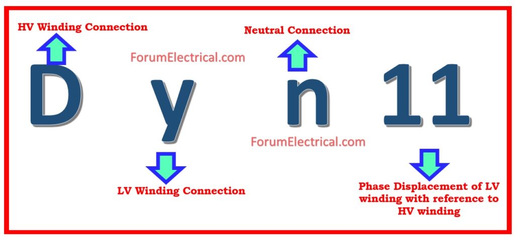
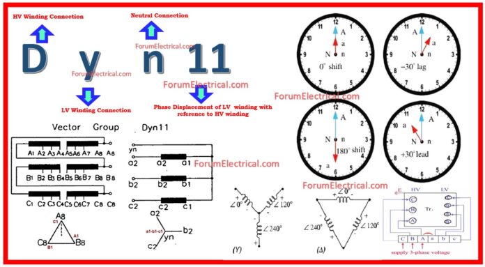
Ex: Dyn11
- D: Delta-connected primary winding.
- y: Star-connected secondary winding.
- n: Neutral point brought out on the star side.
- 11:30° phase shift (clock system).

The International Electrotechnical Commission (IEC) developed the naming system known as the Vector Group of Transformers under IEC 60076-1. This was done to establish a notation for 3-phase transformer winding configuration.
Phase Displacement between HV & LV Windings
The vector for high voltage (HV) winding is used as a reference vector.

The clock hour figure represents the displacement of vectors of other windings from reference vector due to anticlockwise rotation.
IS: 2026 (Part 1V)-1977 specifies 26 sets of connections:
- Star-Star,
- Star-Delta,
- Star Zigzag,
- Delta-Delta,
- Delta Star,
- Delta-Zigzag,
- Zigzag Star, and
- Zigzag-Delta.
The displacement of low voltage (LV) winding vector ranges from zero to -330° in -30° steps, depending on the connecting method.
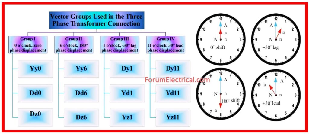
Almost no power system uses such a wide range of connectors. Some regularly used connections include phase displacements of 0, -300, -180″, and -330° (clock-hour settings 0, 1, 6, and 11).
Following the initial appearance of the symbol that represents a high voltage winding, the subsequent winding symbols emerge in a sequence that decreases in voltage.
Ex: a 220/66/11 kV transformer connecting a star, a star, and a delta, as well as vectors of 66 and 11 kV windings with phase displacements of 0° & -330° with reference (220 kV) vector, will be represented as Yy0-Yd11.
With the use of clock face notation, the numerals (0, 1, 11, etc.) depict the phase displacement that occurs across the high voltage and low voltage windings.
The phasor indicating HV winding is used as a reference and set to 12 o’clock.
Phase rotation continues to be counterclockwise. (Internationally adopted).
It is possible to indicate the phase displacement angle by using the hour indicator.
Because a clock has 12 hours and a circle is 360°, each hour symbolizes 30°.
Thus,
- 1 = 30°,
- 2 = 60°,
- 3 = 90°,
- 6 = 180°, and
- 12 = 0° (or 360°).
The minute hand is positioned at 12 o’clock & replaces line to neutral voltage (occasionally imaginary) of the HV winding. This position is continually utilized as a reference.
- Digit 0 =0° indicates LV phasor in phase with HV
- Digit 1 =30° lagging indicates LV lags HV by 30° due to anti-clockwise rotation.
- Digit 11 = 330° indicates 330° lagging (or) 30° leading (LV > HV).
- Digit 5 = 150° indicates LV lags 150° HV.
- Digit 6 = 180° indicates LV lags 180°HV.
Phase Shift of Transformer
It’s essential that parallel transformers have the same phase shift. Transformers can be paralleled at one site and connected to a bus bar (banked) or at different locations with secondary terminals connected via cables and overhead wires.
| Phase Shift (Deg) | Connection | ||
| 0 | Yy0 | Dd0 | Dz0 |
| 30 lag | Yd1 | Dy1 | Yz1 |
| 60 lag | Dd2 | Dz2 | |
| 120 lag | Dd4 | Dz4 | |
| 150 lag | Yd5 | Dy5 | Yz5 |
| 180 lag | Yy6 | Dd6 | Dz6 |
| 150 lead | Yd7 | Dy7 | Yz7 |
| 120 lead | Dd8 | Dz8 | |
| 60 lead | Dd10 | Dz10 | |
| 30 lead | Yd11 | Dy11 | Yz11 |
Why is Vector Group Important?
- System Compatibility: Ensures that transformers can run in parallel without experiencing phase conflicts.
- Load Sharing: Circulating currents are avoided with proper configuration.
- Fault Isolation: Controls how the transformer responds to faults and unbalanced loads.
- Parallel & Phasing Operations: Transformers interconnected in parallel are ensured to be phases correctly using vector group.
- Identification & Prevention of Faults: Through the analysis of voltages and phase relationships, vector groups assist in the identification of transformer failures.
- Interchangeability of transformers: Transformers with same code can be used interchangeably thanks to vector groups.
- Effectiveness & Reliability: Selecting the appropriate vector group in transformer is essential for reliability and efficiency.
Common Vector Groups & their Applications
1). Dyn11
Advantage: Handles unbalanced loads well.
Application: Distribution transformers in power networks.
2). Yyn0
Advantage: Zero phase shift simplifies integration.
Application: Small-scale systems.
3). Dd0
Advantage: No neutral, reducing fault risks.
Application: Industrial setups.
4). Yd1
Advantage: Suitable for connecting high-voltage & low-voltage systems.
Application: Step-down transformers.
How to Identify Vector Group?
Transformer Vector Group Test
Measure the secondary side after applying small voltage to primary winding.
Clock Method
Utilize the clock face analogy, with 12 representing no phase shift.
Dyn11 signifies secondary leads primary by 30° (11 o’clock).
Practical Example
Consider a grid connection using two transformers:
- T1: Dyn11
- T2: Dyn1
If connected in parallel, 60° phase difference might generate circulating currents, resulting in losses and instability. It is essential to ensure that the transformer vector group are compatible.
In order to develop and operate power systems that are efficient, it is essential to have a solid understanding of vector group transformer.
Transformers are ensured to function without any interruptions, faults are minimized, and performance is enhanced.
What is the Vector Group of Step-Up Transformers?
Medium voltage transformers are often constructed with a DELTA-WYE (Delta-Star) vector group when intended for step-down operation and a WYE-WYE (Star-Star) vector group when intended for step-up operation.
What is meant by Dyn11 Vector Group?
Dyn11 illustrates a transformer with delta-connected HV winding & a star-connected LV winding.
It provides voltage transformation versatility and is appropriate for applications that require a higher voltage (HV) step-up (or) step-down.


