
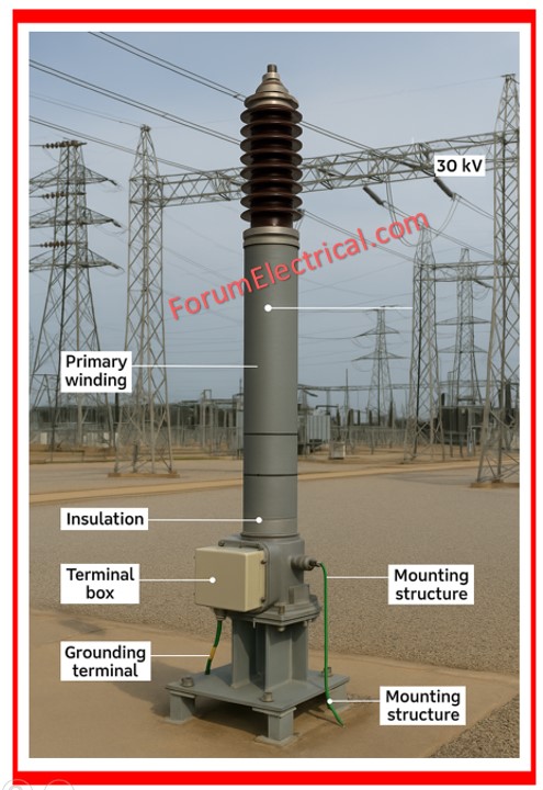
1). What is CT?
A Current Transformer (CT) is an instrument transformer that reduces large currents to a safe, quantifiable level for metering and protection systems.
It develops the primary current on a smaller scale in its secondary winding.
2). What are Errors of CT?
CT errors result from imperfect transformation & include:
- Ratio Error
- Phase Angle Error
- Magnetization Error
Ratio Error is the difference between the actual and expected secondary current values.
Phase Angle Error is the difference in phase between primary & secondary currents.
Magnetization Error is generated by core saturation, particularly at high current levels.
3). What is Ratio & Phase Angle Error of CT?
The ratio error is the discrepancy between the actual & ideal transformation ratios, which is commonly given as a percentage.
The angular difference between secondary & primary current, known as phase angle error, is essential for the accurate operation of protective relays.
4). Draw & Explain the Knee Point Test Characteristics of CT
The Knee Point Test detects the saturation point of the CT core.
Plot the applied voltage versus the magnetizing current.
The “knee point” occurs when a slight rise in voltage induces a significant increase in current, signifying core saturation.
Used mostly for Protection Class CTs.
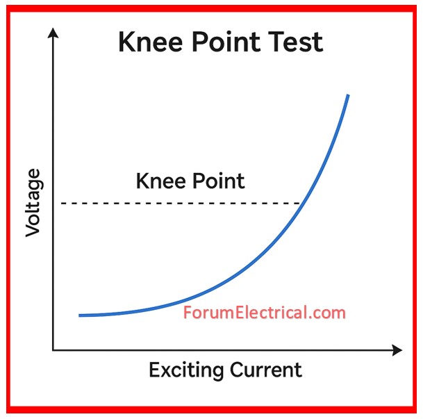
(X-axis = exciting current; Y-axis = voltage.)
The curve rises rapidly after the knee point.
5). Explain Procedure of Ratio Test for CT
Apply a known current (say, 100A) into the primary.
Measure the secondary current.
Compare to the rated transformation ratio.
Calculate the Error:
Ratio Error = [(Ip/N) – Is]/ (Ip/N)
6). What are Tests of Transformer?
- Insulation Resistance Test
- Turns Ratio Test
- Vector Group Test
- Winding Resistance Measurement
- Magnetization Current Test
- Oil Dielectric Test
- Tan Delta and Capacitance Test
- Short Circuit Impedance Test
- Partial Discharge Test
7). Explain Vector Group Test of Transformer
The Vector Group Test determines the winding configuration & phase displacement between the primary and secondary sides.
Apply three-phase voltage.
Take line-to-line voltages across HV & LV.
Phase shifts validate the group (for example, Dyn11, YNd1).
Ideal for paralleling transformers & relay synchronization.
8). What are Tests of VT?
- Ratio Test
- Polarity Test
- Insulation Resistance Test
- Magnetization Curve Test
- Burden & Accuracy Test
- Partial Discharge Test
9). What are different types of VT?
- Electromagnetic VT: A typical iron-core design.
- Capacitor VT (CVT): Utilized for high voltages for power line communication.
- Optical VT: Optical VT employs optical sensors to monitor voltage.
- Inductive VT: standard voltage scaling transformer for metering & protection.
- Electromagnetic VT: traditional, iron-core design.
10). What are the minimum requirements for OC & EF Protection?
Overcurrent (OC):
- Current pickup setting (typically 120%-150% of FLC).
- Time delay (definite or inverse)
Earth Fault(EF):
- Sensitive setting (20%-40% rated current)
- Instant or delayed operation
- CT secondary grounding is necessary.
11). Explain: Under Frequency Function
The Under Frequency (81U) relay function prevents generators and systems from running at low frequencies, which can cause mechanical stress and instability.
It initiates load shedding to restore frequency balance.
The typical setting is 48-49 Hz with a time delay.
12). DC & AC Supervision Relay – Explain
The DC Supervision Relay monitors the control supply (for example, 110V DC) and generates an alarm if it is lost or low.
The AC Supervision Relay ensures that an auxiliary AC supply (such as for indicator lighting or heaters) is present.
These relays are crucial for detecting supply failures before the protective system is damaged.
13). Explain Procedure for Polarity Test of CT
- Connect a DC battery to the primary winding temporarily.
- On the secondary side, use a galvanometer to observe needle deflection.
- The initial kick direction shows polarity.
- Used to provide accurate CT terminal marking (P1-P2, S1-S2).
14). What are Composite Error for CT?
The composite error is the vector difference between the ideal & actual secondary currents under a certain burden and fault current.
This includes:
- Ratio error
- Phase angle error
- Remanence error
Used to classify Protection Class CTs (5P, 10P, PX, etc.).
15). Explain Purpose of Devices – Terminal Block, Relay Output Contacts, Link, DC Supervision Relay.
- a). Terminal Block: A wire connection interface that facilitates maintenance.
- b). Relay Output Contacts: Used to initiate tripping (or) alarms; NO/NC contacts available.
- c). Link: A removable bridge that isolates circuit components for testing (or) protection.
- d). DC Supervision Relay: Monitors the health of the DC control supply.
16). Explain Auto Recloser Functions & Operating Sequence
Auto Recloser automatically restores power after a temporary fault.
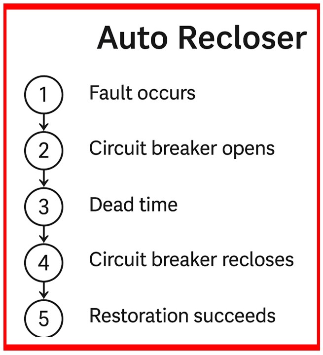
Operating Sequence:
- Fault arises, and the breaker trips.
- The breaker recloses after a time delay.
- If the error persists, retry up to the predetermined count.
- If the permanent fault continues, this will be the final voyage.
- Reduces the probability of outages caused by transient problems.
17). Draw the Characteristics of IDMT & DMT
IDMT (Inverse Definite Minimum Time) describes how operating time reduces as fault current increases.
DMT (Definite Minimum Time): A fixed time delay regardless of the current magnitude.

(Diagram: X-axis = fault current; Y-axis = time.)
IDMT exhibits a downward curve, whereas DMT is horizontal.
18). Explain Over Voltage & Under Voltage Function
- Over Voltage: Operates when the voltage exceeds a safe level. Utilized for equipment protection.
- Under Voltage: Triggers or sounds an alarm when the voltage falls below a certain threshold, which is frequently used to prevent motor stalling (or) contactor dropout.
Both are programmable, with fixed points as well as delays.
19). What is a Burden in CT and why is it important?
The burden of a CT is the load linked to its secondary, measured in VA (Volt-Ampere). It comprises the impedance of all linked
- Relays,
- Meters, and
- Secondary wiring.
If the burden exceeds the rated value, it may cause more mistakes and saturation of the CT, jeopardizing accuracy and dependability.
20). Why should CT secondary not be kept open?
When a CT secondary is open-circuited under load, it might result in high voltage across the terminals due to the transformer’s action.
This can damage insulation, endanger staff, or possibly destroy the CT. When not linked to a load, always short the secondary with a shorting link.
21). What is the Saturation Point of a CT?
The saturation point refers to the secondary voltage at which the CT core reaches saturation & current no longer increases linearly with the primary current.
It is essential to ensure that the CT performs properly during fault circumstances and does not interfere with the protective system.
22). How to perform a Magnetization (Excitation) Curve Test of CT?
To do this test, gradually increase the AC voltage applied to the CT secondary while keeping the primary open, and measure the current.
The magnetization curve is obtained by plotting the voltage vs current. The knee point is the voltage at which a 10% rise in voltage equals a 50% increase in current.
23). What is the principle of Differential Protection?
Differential protection follows Kirchhoff’s current law, which states that the sum of currents entering & exiting a zone should be zero.
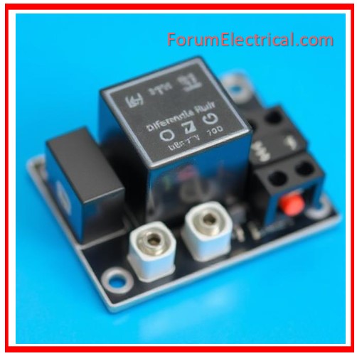
CTs are linked at both ends of a protected zone (e.g., transformer), & the differential relay activates if the difference exceeds a certain threshold, signaling an internal fault.
24). What is a Stabilizing Resistor in a protection circuit?
Stabilizing resistors restrict CT secondary current under saturation or transient circumstances, preventing high impedance differential protection relays from malfunctioning. It maintains the relay operation during through-fault conditions.
25). What is Zone Protection in Substations?
Zone protection splits the power system into defined zones such as bus, line, transformer, and generator.
Relays are programmed to respond exclusively to problems inside their designated zone, ensuring selectivity and synchronization.

, and voltage transformers (VT). Perfect for substation engineers & relay workers getting ready for technical tests or job interviews.)