
Electrical systems needs to be properly protected to ensure that they operate safely and continuously.
The overload relay is one of the most essential relay serve an important part in saving electrical motors & circuits from the adverse impacts of overload.
- What Is an Overload Relay?
- Working Principle of Overload Relay
- 1). Current Flow Monitoring
- 2). Heat Effect
- 3). Bimetallic Strip Action
- 4). Trip Mechanism
- 5). Resetting
- Overload Relay Connection Diagram
- Function of Overload Relay
- What is the Trip Class of Overload Relay?
- Types of Overload Relays
- 1). Thermal Overload Relay
- 1a). Bimetallic Thermal Overload Relay
- 2). Magnetic Overload Relay
- 2a). Electronic Overload Relay
- Eutectic Overload Relay
- Fridge Overload Relay
- Reference Standards
In this post, we’ll look at the different types of overload relays, what they’re used to do, where they’re employed and the protective concept that keeps the electrical system secure.
What Is an Overload Relay?
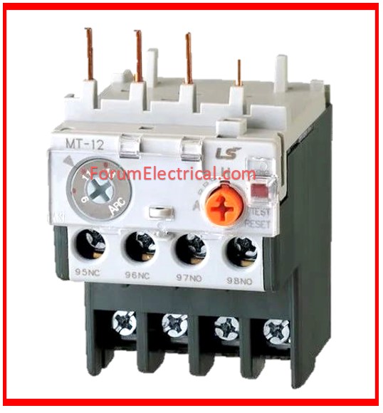
An overload relay is an electrical device that prevents an electric motor from overheating.

Therefore, it is necessary to have enough motor protection.
- Overload Relays,
- Fuses &
- Circuit Breakers
are used to safely operate an electrical motor.
However, this relay just protects the motor, while the circuit breaker or fuse protects the entire circuit.
More specifically, fuses and circuit breakers are designed to detect overcurrent inside a circuit whereas relays are designed to detect over heat if an electric motor overheats.
Eg: An overload relay may explore without tripping a circuit breaker. One does not restore the other.
An overload relay (OLR) is a safety device used in motor control circuits for protecting the motor from damage caused by overcurrent because of overload conditions (where the motor draws more electrical current than its rated capacity for a period of time).
An overload relay is an electrical device that is primarily meant to imitate the heating prototypes of electric motors while also interrupting the current flow when the heat detection device in the relay reaches a fixed temperature.
The design of an overload relay can be done using a heater and normally locked connections that unlock when the heater becomes too hot.
This relay’s connections can be made in series (or) between the motor and the contactor to prevent the motor from restarting when overload is tripped.
Working Principle of Overload Relay
An overload relay works by protecting electric motors & circuits from persistent overcurrent conditions (not short circuits, but overloads). It operates as follows:
1). Current Flow Monitoring
2). Heat Effect
3). Bimetallic Strip Action
4). Trip Mechanism
5). Resetting
1). Current Flow Monitoring
The overload relay is linked in series with a motor. When current passes through a motor, it also passes through the overload relay.
2). Heat Effect
Most overload relays operate on the heating concept.
If the motor current surpasses its rated value over an extended length of time, it generates heat in the relay’s bimetallic strip.
3). Bimetallic Strip Action
The bimetallic strip bends when heated (because 2 metals expand differently).
After a certain time delay (to avoid tripping on minor current changes), the strip bends enough to activate a trip mechanism.
4). Trip Mechanism
The relay opens control circuit (typically the coil of the contactor that controls the motor).
This disconnects the motor from power source, preventing it from overheating and damage.
5). Resetting
The overload relay may be reset manually (with a button press) or automatically (after cooling).
Overload Relay Connection Diagram
The wiring schematic for an overload relay is illustrated below:

Function of Overload Relay
Although there are various types of overload relays on the market, the most common is the “bimetallic thermal overload relay”.
This relay can be designed utilizing 2 different types of metal strips which can be joined together and enlarge at different rates when heated.
Once the strip is heated to a specific temperature, it can twist far enough to break the circuit.
When the current flow to the motor exceeds the capacity of the heaters the overload occurs after a few seconds.
Eg: If the overload relay explores within a bimetallic relay, the NC (normally closed) bimetallic connections will release the circuit until the strip cools down.
If someone tries to close the contactor switches by pressing the start switch, the motor will not turn on.
What is the Trip Class of Overload Relay?
The trip class denotes the time it takes to unlock contactor during overloads.
Overload relays are classed into 3 categories depending on the duration of the relay explore.
•Class 10 Overload Relays,
•Class 20 Overload Relays &
•Class 30 Overload Relays
can be evaluated after 10 seconds, 20 seconds & 30 seconds respectively. One key security feature of this relay is that it prevents the motor from restarting immediately.
Class 10 and 20 overload relays are widely utilized.
Class 30 OLR is primarily used to protect motors when operating at high idleness loads.
Class 5 relays are utilized for motors that require extremely fast tripping.
| Class | Time to trip from a cold start at 1.05 × Ir | 1.2 × Ir | 1.5 × Ir | 7.2 × Ir |
| 10A | > 2 hr | < 2 hr | < 2 min | 2 s < t < 10 s |
| 10 | > 2 hr | < 2 hr | < 4 min | 2 s < t < 10 s |
| 20 | > 2 hr | < 2 hr | < 8 min | 2 s < t < 20 s |
| 30 | > 2 hr | < 2 hr | < 12 min | 2 s < t < 30 s |

Types of Overload Relays
Overload Relay Types:
These are divided into different types:
1). Thermal Overload Relay
A thermal type relay is a protection device that is primarily meant to turn off the power when the motor consumes an excessive amount of current for an extended period.
To do this, these relays have an NC (normally closed) relay. Once extreme current is supplied via the motor circuit, the relay opens due to
- Improved motor temperature,
- Relay temperature,
- Detected overload current
- Depending on the type of relay.
These relays are linked to circuit breakers in both structure and application; however most circuit breakers disrupt the circuit if an overload occurs, even for a brief period.
These are also designed to calculate the motor’s heating curve; hence, overload should occur for an entire duration before circuit is broken up.
Thermal overload relays are split into 2 types:
- Solder Pot Thermal Overload Relay and
- Bimetal Strip Thermal Overload Relay.

1a). Bimetallic Thermal Overload Relay
A bimetallic thermal overload relay’s operation is mostly determined by the heating properties of the bimetallic strip.
In the direct heating method, the overload relay, also known as OLR can supply the entire current flow to the motor.
As a result, it is immediately heated by the current flow.
However, if direct heating is not desired, the strip can be brought into close contact via the relay’s conductor.
The conductor and bimetallic strip heat the intense current flow toward the electric motor.
The conductor in this case will be insulated thus no current will flow through the strip.
2). Magnetic Overload Relay
Magnetic overload relays can be activated by measuring the magnetic field intensity produced by the current flow toward the motor.
This relay can be designed with a changeable magnetic core within a coil that stores motor current.
The flux arrangement within the coil drags the core upwards.
As the core progresses far enough, it triggers a series of connections at the relay’s highest point.
The primary difference between thermal and magnetic type relays is which magnetic overload relays are insensitive to ambient temperature.
In general, these are employed in places where the ambient temperature fluctuates dramatically.
Magnetic Overload Relays are split into two types:
- Electronic Magnetic Overload Relays and
- Dashpot Magnetic Overload Relays.
2a). Electronic Overload Relay
Electronic overload relays are commonly known as solid-state overload relays.
There is no bimetallic strip on the inside of any of these relays.
As an alternative, it incorporates current transformers (or) temperature sensors to detect the total current flow toward the motor.
This type of relay protects itself using microprocessor technology.
Here, PTC (Positive Temperature Coefficient sensor) plays an important role in detecting temperature and tripping the circuit when overload faults arise.
Some overload relays have
- Hall Effect sensors and
- Current Transformers
that sense the current flow directly.
The fundamental advantage of an electronic overload relay is that it lacks the bimetallic strip resulting in less heat loss in the relay.
Furthermore, these relays outperform thermal relays in terms of accuracy.
Some electronic OLD manufacturers design their products with additional features such as earth fault and motor stall protection.
Electronic overload relays are utilized when motors need to be started and stopped regularly.
These relays can be designed to resist the motor’s starting current for a specific period of time.
Eutectic Overload Relay
The eutectic overload relay consists of
- Winding heater,
- Eutectic alloy &
- Mechanical device for activating the tripping mechanism.
A eutectic alloy is a combination of two or more materials that melts and hardens at a certain temperature.
In the OLR, the eutectic alloy is encased in a tube and used repeatedly via a ratchet wheel loaded with a spring to activate the tripping device during the overload phase.
Throughout the overload, the current in motor supplies the small heater winding, which heats the eutectic alloy tube and causes the alloy to dissolve, causing the ratchet wheel to turn.
This process starts to open the OLR’s closed auxiliary contacts.
Once the tripping is complete, these relays can be manually reset. So, typically, this reset may be performed using a reset button located on the relay cover.
The heater unit connected to the relay can be chosen based on the motor’s total load current.
Fridge Overload Relay
A protection device such as an overload relay is employed in the refrigerator’s compressor circuit.
The power supply is provided to the compressor motor’s windings via the overloading machine.
This type of relay is mostly used to incorporate the start winding into the circuit until the compressor is working at full speed.
Reference Standards
IEC 60947-4-2: Electronic overload relays and motor protection devices.
ANSI / NEMA ICS 2: Specifies performance & construction requirements for overload relays utilization in motor circuits.
IS/IEC 60947-4-1: Adopted from IEC, covering electromechanical contactors & motor starters with overload protection.

