
- What is Relay?
- Working Principle of Relay
- Construction of a Relay
- Terminals for Relay
- 1). Control input (or) Coil Terminals
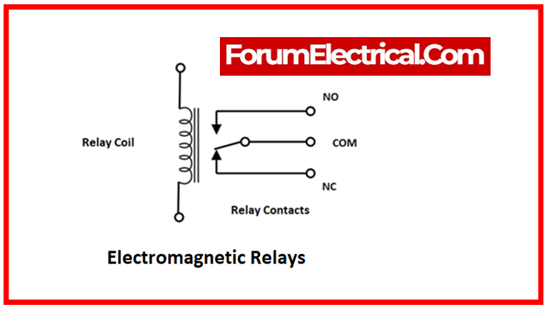
- 2). COM or Common Terminal
- 3). NO Terminal
- 4). NC Terminal
- Poles and Throw
- Operation of a Relay
- Different Types of Relay
- Based on Poles and Throw
- 1). SPST Relay
- 2). SPDT Relay
- 3). DPST Relay
- 4). DPDT Relay
- Based on Forms of Relay
- 1). “Form A” Relay
- 2). “Form B” Relay
- 3). “Form C” Relay
- 4). “Form D” Relay
- Based on Operating Principles
- 1). Electromechanical Relay (EMR Relay)
- 2). Solid-State Relay (SSR Relay)
- 3). Hybrid Relay
- 4). Electro-Thermal Relay (Thermal Relay)
- 5). Reed Relay
- 6). Latching Relay
- 7). High-Voltage Relay
- 8). Time Relay
- 9). Current and Voltage Relays
- 10). Differential Relay
- 11). Distance Relay
- 12). Frequency Relay
- 13). Microprocessor-Based Relay
- 14). Sequence Relay
- 15). Rotary Relay
- 16). Moving Coil Relay
- 17). Target Annunciator Relay
- 18).Flash Relay
- 19). Buchholz Relay
- 20). Safety Relays
- 21). Ground-Fault Relay
- 22). Supervisory Relay
- 23). Power Factor Relay
- 24). Mho Relay
- 25). Overcurrent Relay
- Based on Polarity
- 1). Polarized Relay
- 2).Non-Polarized Relay
- Application of Relay
What is Relay?
Relays regulate circuits with one minimal power signal or numerous circuits with one signal. Long telegraph circuits, like signal repeaters, first employed relays to activate and transmit waves. Most telephone exchanges and early computers used relays.
Relays are the main protection & switching mechanisms in most control procedures and equipment. All relays open or close contacts or circuits in response to voltage or current. Relays isolate or modify electric circuit conditions.
The relay ensures that the circuit is protected so that no damage occurs. Every relay consists of three critical components:
- Computed,
- Comparing, &
- Controlling components.
The computed component understands the variation in the real measurement, & the comparing component compares the actual amount to that of a predetermined relay.
The controlling component also manages rapid changes in the measured capacity, such as the closure of the present functional circuit.
Reclosing relays link system network components and devices, such as the synchronization process, & restore them when electrical faults are repaired, followed by transformer and feeder connections to the line network. Like tap-changing transformers, regulating relays enhance voltage by contacting each other.
Auxiliary contacts multiply contact points in circuit breakers and other safety devices. System conditions like power direction trigger alerts from monitoring relays. These are directional relays.
Traditional relays utilize an electromagnet to open & close connections, but solid-state relays employ semiconductors alternatively.
To prevent overload currents, electric circuit systems use calibrated relays and functional coils. Digital devices called protective relays perform these functions in modern electrical circuits.
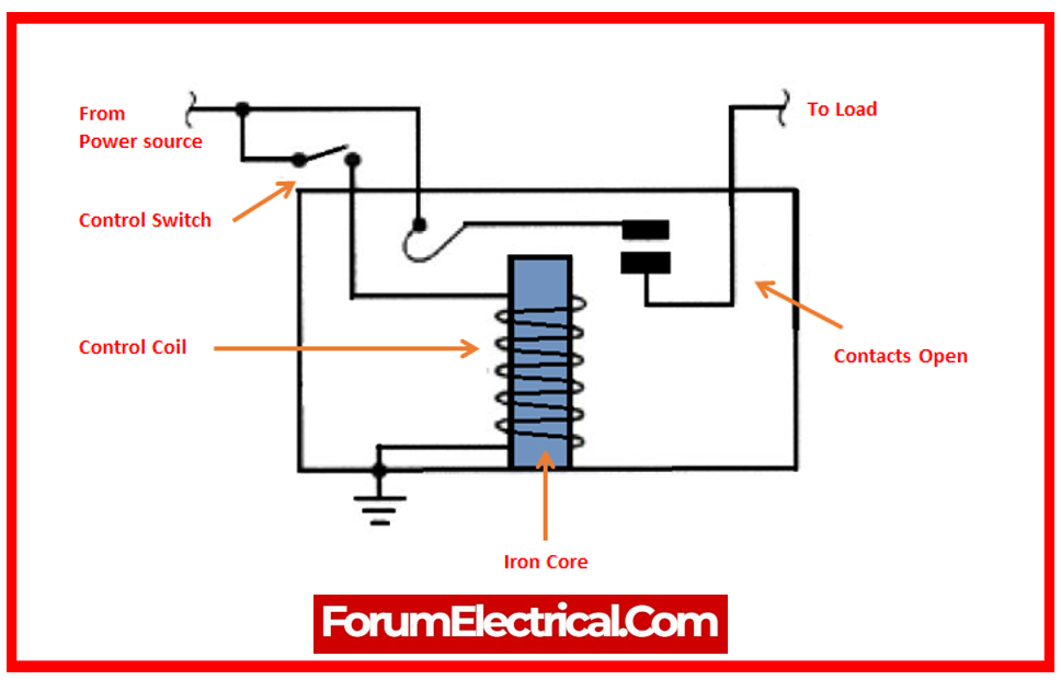
Working Principle of Relay
It operates on the basis of electromagnetic attraction. When the relay circuit detects a fault current, it activates the electromagnetic field, resulting in a temporary magnetic field.
This magnetic field moves relay armature, which opens or closes the connections. The small power relay has only one contact, but the high power relay has two contacts that open the switch.
It has an iron core that is coiled with a control coil. The coil receives electricity through the load’s connections & the control switch. As electricity passes through the coil, a magnetic field develops.
Because of this magnetic field, the magnet’s higher arm draws the lower arm. Close the circuit, allowing the current to flow via the load. When the contact is already closed, it moves in the opposite direction, thereby opening the contacts.
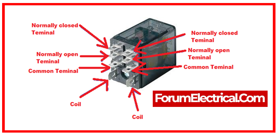
Construction of a Relay
To understand the basic design and internal components of a relay, the corresponding diagram shows an inside perspective of a relay.
Terminals for Relay
A relay typically has four different types of terminals.
- Control input (or) Coil Terminals
- COM or Common Terminal
- NO Terminal
- NC Terminal
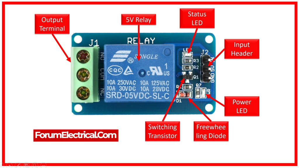
1). Control input (or) Coil Terminals
A relay has two control input terminals that control switching.
A low-voltage power source is linked to these terminals to activate & deactivate the relay. The supply might be either AC or DC, based on the type of relay.
2). COM or Common Terminal
COM relates to the relay’s common terminal.
This is the relay’s output terminal, which connects one end of load circuit.
This terminal has an internal connection to one of the other 2 terminals, depending on the status of the relay.
3). NO Terminal
NO, or Normally Open, is a relay load terminal that remains open even when the relay is not active.
When the relay is activated, the NO terminal closes along with the COM terminal.
4). NC Terminal
The NC, or Normally Closed terminal, is a relay’s other load terminal. When no control input is available, this terminal is generally connected to the relay’s COM terminal.
When the relay activates, the NC terminal separates from the COM terminal and remains open until the relay is terminated.
Poles and Throw
Poles are the switches within a relay.
The number of switches within a relay is referred to as its poles.
The throw of a relay refers to the number of circuits operated by each pole.
A single throw relay can only control one circuit, either OFF or ON, whereas a double throw relay may control two circuits, alternating between them by opening one and closing the other during switching.
Operation of a Relay
In the case that there is no source of power, the relay will remain inactive, & the position of its pole will remain at the NC terminal. In the case described above, the NC terminal is the upper terminal.
A path that is electrically short is created as a consequence of this between the COM terminal & the NC terminal. This makes it possible for current to flow through the circuit that is connected to the COM terminal and the NC terminal.
A low voltage source is used to power the relay, and when this occurs, the pole of the relay moves to the NO terminal. It is because of this that the NC terminal opens up, whereas the COM terminal either closes down or becomes electrically short to the NO terminal.
After that, enabling the flow of electricity via the circuit that is connected with the COM terminal and the NO terminal simultaneously. By this way the relay function.
Different Types of Relay
Different types of relays are classed based on their features. Each relay type is created for a certain application, therefore choosing the right one before using it in a circuit is important.
Based on Poles and Throw
Relay types are classed based on the number of poles and throws.
- SPST Relay
- SPDT Relay
- DPST Relay
- DPDT Relay
1). SPST Relay
SPST – Single Pole, Single Throw Relay
The term single pole refers to the ability to regulate only one circuit, whereas single throw refers to the fact that the pole can only conduct in one position. The SPST relay has two states: either open or closed circuit.
2). SPDT Relay
SPDT – Single Pole, Double Throw Relay
The single pole indicates that it can only regulate one circuit at a time. The double throw refers to the pole’s ability to perform in two positions.
The SPDT relay has two states, in which one circuit is closed while the other is open, and vice versa.

3). DPST Relay
DPST – Double Pole Single Throw Relay
The double pole allows it to manage two entirely isolated individual circuits. The term single throw refers to the requirement that each pole can conduct in only one position.
The DPST relay may switch two circuits at once, providing either a closed or open circuit.
4). DPDT Relay
DPDT – Double Pole, Double Throw Relay
The double pole indicates it can control two circuits, and the double throw implies each pole is able to conduct in two distinct positions.
The DPDT relay can be regarded as two SPDT relays, however their switching occurs simultaneously.
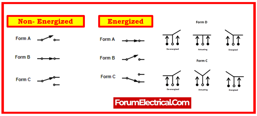
Based on Forms of Relay
Relays are further categorized according to their configuration, which is known as “Forms”.
- “Form A” Relay
- “Form B” Relay
- “Form C” Relay
- “Form D” Relay
1). “Form A” Relay
“Form A” is an SPST relay with a normally open (NO) by default condition.
It has a NO terminal that’s connected to the circuit whenever the relay is triggered and disconnects when the relay is turned off.
2). “Form B” Relay
Form B relay is an SPST relay with a normally closed (NC) by default condition.
The NC terminal links the circuit whenever the relay is inactive & disconnects it when the relay is activated.
3). “Form C” Relay
Form C relays are SPDT relays with double-throw contact terminals (NC and NO).
It regulates two circuits, one of which remains open and the other closed. It is also called a “break-before-make” relay because it opens one circuit before closing another.
4). “Form D” Relay
Form D relays are SPDT relays that operate on the same concept as Form C relays, but they are “make-before-break” contact relays.
It closes the following circuit prior to breaking (opening) the preceding one. It is utilized to ensure that the circuit’s continuity remains intact.
Based on Operating Principles
The following types of relays are categorized according to their respective operating principles.
1). Electromechanical Relay (EMR Relay)
2). Solid-State Relay (SSR Relay)
3). Hybrid Relay
4). Electro-Thermal Relay (Thermal Relay)
5). Reed Relay
6). Latching Relay
7). High-Voltage Relay
8). Time Relay
9). Current and Voltage Relays
10). Differential Relay
11). Distance Relay
12). Frequency Relay
13). Microprocessor-Based Relay
14). Sequence Relay
15). Rotary Relay
16). Moving Coil Relay
17). Target annunciator Relay
18).Flash Relay
19). Buchholz Relay
20). Safety Relays
21). Ground-Fault Relay
22). Supervisory Relay
23). Power Factor Relay
24). Mho Relay
25). Overcurrent Relay
1). Electromechanical Relay (EMR Relay)
The Electromechanical Relay (EMR) consists of an electromagnetic coil & a mechanically moveable contact.
When energized, the coil generates a magnetic field. This magnetic field attracts the armature (moving contact). When the coil is de-energized, the magnetic field dissipates and a spring retracts the armature to its original position.
The EMR relay is intended for either an AC or a DC power source, depending on the application. The constitution of an AC and a DC EMR relay differs slightly in terms of coil fabrication. The DC coil possesses a freewheeling diode to prevent against back EMF & de-energize the coil.
The polarity of the source in an EMR relay is irrelevant; it will power the coil in either direction; however, if a back EMF diode is fitted, polarity must be considered.
The fundamental downside of an EMR relay is that each of its contacts form an arc when they break, increasing resistance over time & reducing the relay’s lifespan.
Different Relays in Electromagnetic Types
These relays are made of electrical, mechanical, & magnetic components, with an operational coil & mechanical contacts. As a result, when the coil is energized by a power supply, these mechanical contacts open or close. The supply can be either AC or DC. These electromagnetic relays are additionally characterized as
- DC vs AC Relay
- Attraction Type Relay
- Induction type Relay
DC vs AC Relays – Both AC and DC relays operate on the same electromagnetic induction principle, but their construction differs and is also determined by the application in which they are used. DC relays use a freewheeling diode to de-energize the coil, while AC relays use laminated cores to reduce eddy current losses.
The most noteworthy element of an alternating current is that the direction of current source changes every half cycle; as a result, the coil loses magnetic every cycle because the zero current causes the relay to repeatedly make and break the circuit. To prevent this, one shaded coil or similar electronic circuit is added to the AC relay to supply magnetism when the current is zero.
Attraction-Type Electromagnetic Relays – When power is applied to the coil, these relays attract a metal bar (or) a part of metal. They can operate on both AC and DC power supplies. This may include a plunger being drawn towards a solenoid or an armature being drawn to the poles of an electromagnet. These relays have no time delays, therefore they are employed for instantaneous operation.
There are further variations in attraction type of an electromagnetic relay, which include:
- Balanced Beam Relay – Two quantifiable quantities are associated here because the resulting electromagnetic pressure changes twice as much as the number of ampere-turns. The ratio of functional current for these relays is quite low. When the device is programmed to operate at high speeds, the relay has a propensity to overshoot.
- Hinged Armature Relay- Inserting a permanent magnet increases the relay’s sensitivity for DC performance. This is also known as a polarized movement relay.
Induction-Type Relays – These can be utilized as protective relays in both AC and DC systems.
The actuation force for contact movement is generated by a moving conductor, which can be a disc or a cup, due to the interaction of electromagnetic fluxes caused by fault currents.
These are classified into numerous varieties, including
- Shaded Pole Relay,
- Watt-Hour Relay and
- Induction Cup Relay
and are mostly employed as directional relays in power-system protection & high-speed switching operation applications. Induction relays are classed according to their structure.
- Shaded Pole Relay – A structured pole is typically activated by flow of current in a single coil wound on a magnetic structure with an air gap. The air gap instabilities caused by the adjusting current are divided into two fluxes separated by a shaded pole & in time-space. This shaded ring is made of copper material and surrounds each portion of the pole.
- Watt-Hour Relay – Watt-Hour Relay commonly known as Watt/hr Meter, is a sort of relay that has an E & U-shaped electromagnet with a disc-free to revolve between the electromagnets. The phase shift between fluxes produced by the electromagnet is accomplished by the developed flux of 2 electromagnets, each with a different resistance inductance value for both circuit systems.
- Induction Cup Relay – This device is based on electromagnetic induction theory. The gadget consists of two or more electromagnets, which are activated by the coil in the relay. The revolving magnetic field is created by the coil which surrounds the electromagnet. This revolving magnetic field induces current in the cup, causing it to rotate. The present rotation direction is identical to the cup’s rotation direction.
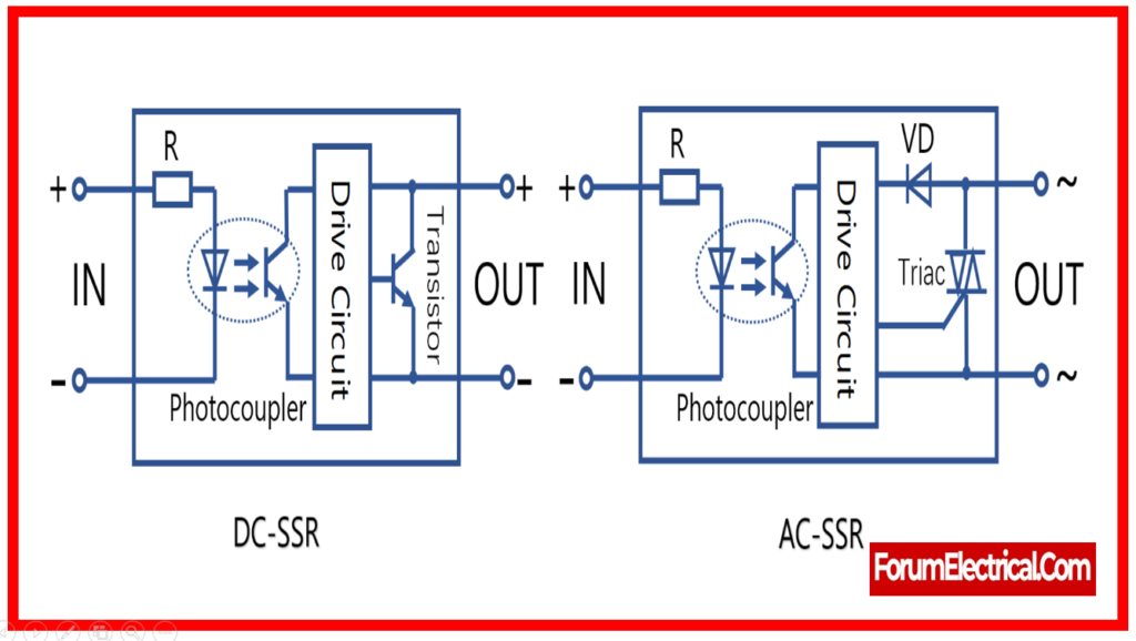
2). Solid-State Relay (SSR Relay)
SSR relays are constructed of semiconductors rather than mechanical parts and work by isolating the low voltage circuit from the high voltage circuit via an opto-coupler.
When the control input is fed to a solid state relay, an LED lights up, emitting infrared light. This light is detected by a photosensitive semiconductor device, which converts it to an electrical signal & switches the circuit.
SSR runs at a reasonably high speed and consumes very little power when compared to EMR relays. It lasts longer since there are no physical contacts to burn out.
The primary disadvantage of an SSR relay is the nominal voltage drop through the semiconductor, which loses power as heat.
3). Hybrid Relay
Hybrid relays are constructed using both SSR & EMR relays.
As we know, the SSR wastes power in the form of heat, while the EMR has contact arcing issues. To compensate for the shortcomings of SSR and EMR, the hybrid relay employs both technologies.
In Hybrid relay, SSR & EMR are utilized together. A relay control circuit is utilized to flip the SSR initially. The SSR receives the load current. This eliminates the arcing issue.
The control circuit then energizes the EMR coil, causing its contact to close, but there is no arching because the SSR maintains the load parallel. After some time, once the EMR contact has settled down, the SSR control input is deleted. The EMR transmits the complete load current without loss. Because there is no current flow through the SSR and the EMR takes the full load, there is no power loss in the form of heat. As a result, the heat issue is also resolved.
4). Electro-Thermal Relay (Thermal Relay)
An electro-thermal relay is composed of bimetallic (two metals with differing thermal expansion coefficients) strips.
When current flows through a conductor, it generates heat. As a result, the temperature rises and the bimetallic strip expands. Metals with a high thermal expansion coefficient expand more than other metals. As a result, the strip bends & shuts the connections, which typically activates the trip circuits.
Thermal relays are typically utilized for the electric motor protection.
5). Reed Relay
Reed relays have a reed switch, electromagnetic coil, and back EMF diode.
A reed switch consists of two metal blades composed of ferromagnetic material that are hermetically sealed inside a glass tube that additionally supports the metal blades. The glass is full of inert gas.
When the coil is activated, the ferromagnetic metal blades attract each other, forming a closed path. There is no contact wear-out due to the absence of a moving armature. The glass tube is additionally filled with inert gas, which extends its life.
6). Latching Relay
A latching relay is one that is activated by a single current pulse in winding & remains in this condition until the pulse is no longer impacting it, at which point it is locked. As a result, the relay works as a storage circuit. Furthermore, the latching relay reduces power consumption in application circuit by eliminating the need to charge the coil all the time.
7). High-Voltage Relay
The rapid growth of electrical technology using high voltage (power laser, high-frequency metal, industrial accelerator & medium heating, etc.), the usage of power electronic equipment (radar, TV, and radio transmitter) working under high voltage, for various voltage levels The demand for insulation test systems for electrical equipment explains the popularity of high voltage (HV) relays functioning at voltages ranging from 5 to 300 kV and greater. Such relays are classified into two types:
- High-voltage insulated relays for all load current components, &
- Low-voltage & high-voltage insulated relays across the input (control coil) and output (contact).
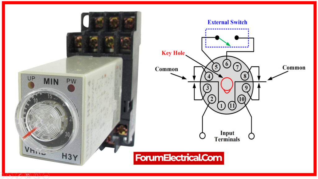
8). Time Relay
Besides electrical relays, the “time relay” is the most commonly used relay. The term “delay relay” is often used because these relays normally delay the relay input signal. Because the relay’s state change is accompanied by a delay in the signal delivered to its input terminal, it may be concluded with accuracy that, in addition to other purposes, each relay also serves as a timing relay.
Automatic control systems’ stability can be improved by using conventional electromechanical relays. Their sole purpose is to give a specific signal delay with a value equal to its own manufacture delay. From an engineering standpoint, a “time relay” or “time delay relay” is typically characterized as a relay that uses a time delay function as its foundation and improves the function’s features in some manner.
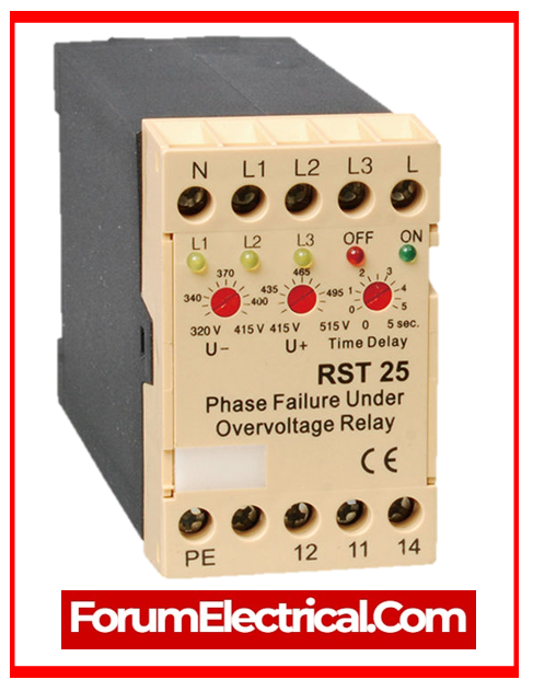
9). Current and Voltage Relays
These relays are specifically intended to manage current (or) voltage levels in both high-voltage and low-voltage circuits, and they provide specified output signals when the current (or) voltage level differs from a predetermined value. These relays are referred to as “measuring relays” because they continuously monitor execution values throughout operation.
Typically, the output signal of this type of relay affects the power shutdown device and cuts off the load, so saving it (or the primary power supply) from harm in the emergency mode, this is why it is also known as a “protective relay”.
10). Differential Relay
Differential protection detects the fault by comparing 2 (or more) currents; this is essentially current protection. In comparison to different kinds of protection, differential current protection has complete selectivity since it can act efficiently only when the fault occurs within the protection region and not at all when the fault occurs outside of the protection area.
The differential relay’s area is restricted by the circuit that connects the CTs it is attached to. Because of the protection’s great selectivity, the relay pickup requires no activation delay, so all differential relays perform high-speed. As a result, differential protection has very high selectivity as well as speed.
11). Distance Relay
An actuator that responds when a predefined circuit admissibility, impedance, (or) reactance is surpassed.
If each relay positioned along the line has a time delay that is proportional to the impedance (distance), the relay picking up initially is always the one nearest to the short circuit location.
Distance protection seeks to do this. In a two-way power supply circuit, distance protection is directional.
12). Frequency Relay
The drop in frequency is due to a power system overload, whereas the increase in frequency indicates excess power. When one or more heavily laden lines fail unexpectedly, there will be extra power in system.
Excess power is routed to other lines, resulting in unsafe power flow that could cause the power system to collapse. This is why managing the voltage frequency is important.
A unique relay controls the frequency, as well as other circuit parameters.
13). Microprocessor-Based Relay
A microprocessor-based relay is a compact computer with output circuit specifications that match external current & voltage transformers. Programming can be done in memory, which allows the operation of a protective relay to be represented using input signals.
At least in the early stages of developing microprocessor-based devices, any relay can be created by making precise changes to the program using a simple general-purpose microprocessor.
14). Sequence Relay
Sequence relays are also known as alternators, step relays, triggers, and pulse relays. The relay can open & close contacts in a specified order.
All sequence relays utilize a ratchet (or) catch mechanism to modify the state of their contacts by sending repeated pulses to a single coil.
Typically, but not constantly one pulse closes a group of contacts, the next opens them, and so on.
15). Rotary Relay
A rotary (or) motor-driven relay is one in which the armature and contacts rotate rather than move forward. In actuality, this is a typical electromagnetically powered multi-contact rotor switch, not a manual one.
16). Moving Coil Relay
This type of relay has an odd outward design, which can resemble a vacuum tube (or) measuring tool. Naturally, this relay resembles a measuring device, as it is a highly accurate sensitive measuring mechanism with extremely sensitive contacts.
The device’s function is determined by the interaction of the permanent magnet’s magnetic field with the current in winding.
The winding is twisted around a rectangular light aluminum tube (frame) sandwiched across the permanent magnet & the iron core ring.
17). Target Annunciator Relay
A signal relay (also known as a target relay (or) flag relay is a device that does not have an automatic reset and only indicates the state of a protection device and can also be set to do the lock function. In simple terms, the target relay is employed in relay protection & automation systems as a signal for other relays to detect.
18).Flash Relay
The flash relay (or) flasher generates the signal lamp’s flickering light. Because of the flicker, it will draw more attention than a bulb that is permanently turned on. This relay is commonly used to drive a single signal bulb and is part of a multi-valve signal board.
19). Buchholz Relay
Buchholz relays are utilized to protect equipment submerged in liquid by monitoring for abnormal flow, no gas, or abnormal gas development (the majority of oil-filled power transformer failures are accompanied by gas production).
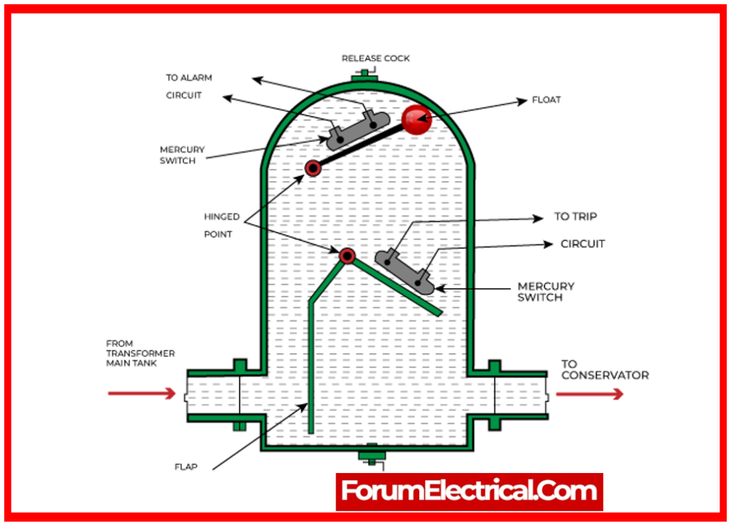
These relays are usually employed in transformers with the expansion tanks.
They gather the gas that is progressively discharged owing to minor internal faults (such as weak connections, short arcs, and so on) till the gas volume activates a switch, which then sends out an alert signal.
Once the gas has been collected and tested, the issue can be recognized.
20). Safety Relays
Electrical relays have numerous components that are susceptible to power, electrical, and thermal deterioration.
In many applications, safety is paramount, and the usage of electrical equipment is vital to ensuring that no unsafe machine movement occurs over the fault indication cycle, whenever a defect is identified by the moving relay contact.
To assure the safety function, particularly in the case of a failure, suitable control is included into the safety device’s circuit. The safety relays which force the contacts serve a key part in preventing accidents in equipment and systems.
21). Ground-Fault Relay
A ground fault relay is an instrument that switches off the power supply when electricity flows to the ground.
As a result, it may protect against damaging electric shocks while also providing a passage to the ground in the event of human contact with the live circuit.
Typical illustrations of these conditions include the use of damaged wires and appliances.
22). Supervisory Relay
The primary function of this relay is to constantly monitor the normal operation of important devices (or crucial power parameters provided to this equipment). These units and parameters include
- The trip coil & power supply of the high-voltage circuit breaker in power grid,
- The sensor power supply circuit of the fire alarm system,
- The phase sequence and phase loss of the motor power supply, and
- The insulation level of electrical equipment, among others.
Monitoring relays can identify interruptions, high resistance due to
- Improper current connections,
- Increased contact transfer resistance,
- Control contact welding,
- Control voltage loss, &
- Relay voltage failure.
23). Power Factor Relay
A relay that activates if the power factor in an alternating current circuit exceeds or falls below a predetermined threshold. It is utilized for power factor adjustment purposes.
24). Mho Relay
A mho Relay is a high-speed relay that is also referred to as an admittance relay. The volt-amperes element provides operating torque in this relay, while the voltage element generates the controlling element. A mho relay is also known as a voltage-controlled directional relay.
25). Overcurrent Relay
The overcurrent relay can be described as a relay that activates only when the current exceeds the relay’s setting time. It protects power system equipment from fault currents.
Based on Polarity
1). Polarized Relay
The polarized relay combines a permanent magnet using an electromagnet. The permanent magnet ensures that the armature remains in position. The electromagnetic coil moves the armature around a fixed pivot. The armature position is determined by the polarity of the control input signal.

2).Non-Polarized Relay
The non-polarized relay doesn’t utilize permanent magnets, therefore its coil can be powered in any direction without impacting its operation.
Some relays with back EMF diodes have polarity, as the diode can bypass the coil when the connection is reversed.
Application of Relay
- Separating a low voltage circuit from a high voltage circuit is accomplished through the utilization of relays.
- They serve the purpose of controlling a number of different circuits.
- It is also possible to employ them as an automatic change over.
- Relays are utilized by microprocessors in order to control a significant electrical load.
- Motors are protected from overload & electrical failure by overload relays, which are utilized for electrical protection.
