")
Protection relays employ a wide range of configurable parameters to identify defects & trip the breaker in a controlled & selected manner.
Understanding each setting facilitates proper relay coordination.
- 1). PSM – Plug Setting Multiplier (Current Setting Multiplier)
- What is PSM?
- 2). TSM – Time Setting Multiplier
- What is TSM?
- 3). OL – Overload Setting (Thermal Overload)
- 4). EL – Earth Leakage Setting / Earth Fault Pickup
- What is EL (Earth Leakage / Earth Fault)?
- 5). MF – Multiplying Factor (Metering Factor / Scaling Factor)
- How these setting work together in a Relay?
- Practical Example: Complete Relay Setting Coordination
1). PSM – Plug Setting Multiplier (Current Setting Multiplier)
What is PSM?
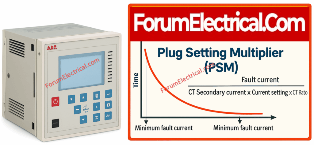
PSM represents how many times the actual current is above the relay’s current pickup setting.
Plug Setting Multiplier (PSM) indicates how many times the determined relay secondary current (typically the CT secondary) exceeds the relay pickup (plug) current.
It is the key quantity utilized in IDMT (inverse definite minimum time) curves to calculate the basic operating time.
PSM (Plug Setting Multiplier) settings must be in accordance with IEC 60255-151 which specifies performance standards for overcurrent relays and the computation of operational characteristics based on fault current.
Formula
PSM = Fault Current/Pick Up Current
Pickup Current= Current Setting x CT Secondary
Example
• CT: 400/5A
• Current setting (Plug setting): 120%
• Actual fault current = 10A (secondary)
Pickup=1.2×5=6A
PSM =10/6= 1.67
Application of PSM
• Determines how fast the relay operates based on the IDMT curve.
• Higher PSM implies faster trip.
2). TSM – Time Setting Multiplier
What is TSM?
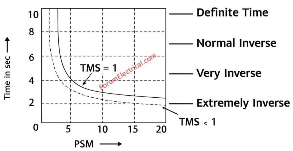
Time Setting Multiplier (TSM) scales the base time calculated from the relay’s characteristic curves.
The curve provides a base operating time for a particular PSM which TSM multiplies to provide the actual trip time.
TSM (Time Setting Multiplier) selection should adhere to IEC 60255-3 which defines the standard inverse, very inverse & extremely inverse IDMT time-current characteristics utilized for relay coordination.
Formula
Actual Trip Time = TSM x Curve Time
Purpose
• Achieves proper coordination between relays (upstream & downstream)
• It’s the mechanism used to construct time grading across relays that make the downstream relay TSM small and the upstream relay TSM larger so that the upstream relay can give backup.
• Lower TSM = faster tripping.
• Typical range: 0.1 to 1.0.
Example
If the IDMT curve time = 2.4 sec and
TSM = 0.2
Trip time = 0.2 x 2.4 = 0.48
3). OL – Overload Setting (Thermal Overload)
Overload Setting is a thermal/long-term overcurrent element (I²based).
It guards against sustained overcurrent which produces heating (thermal & mechanical stress), rather than immediate faults.
Used mainly in motor protection relays & some transformer relays.
OL (Overload / Thermal Overload) settings must adhere to the thermal protection principles described in IEC 60255-8 and IEC 60947-4-1 which define I²t characteristics and tripping curves for motor and equipment overload protection.

How it Works?
The thermal model calculates damage as the integral of squared current over time (I²t).
The relay has an overload pickup (often represented as a percentage of rated (or) FLA & a thermal time constant/curve that specifies how long it takes to trip at a given multiple of rating.
Not an instant trip – has a thermal curve.
Function
Protects equipment against:
• Long-duration overcurrent,
• Heating,
• Mechanical damage.
Typical Settings
• Motor protection: 90–110% of FLA
• Transformer protection: 110–130% of rated current
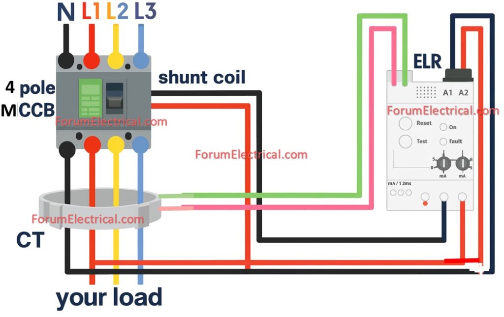
4). EL – Earth Leakage Setting / Earth Fault Pickup
What is EL (Earth Leakage / Earth Fault)?
Threshold current at which the relay detects earth fault.
EL is the threshold (in A) in which the relay detects an earth (or) ground fault.
In medium/high-voltage systems, this is frequently a percentage of CT primary or an actual secondary current value that is depending on whether residual (or) zero-sequence detection is employed.
IEC 61008, IEC 61009 & IEC 60255-151 describe the sensitivity, trip limits & performance parameters for earth-leakage & earth-fault protection devices.
Formula
Earth Fault Pickup = EL Setting x CT Secondary
Typical Values
• LV systems: 30mA – 1A (ELCB/RCCB)
• Industrial LV: 10A – 50A
• MV relays: 10% – 40% of CT primary (sensitive EF)
Purpose
• EL can prevent against insulation failure & earth faults which can cause fires or other issues.
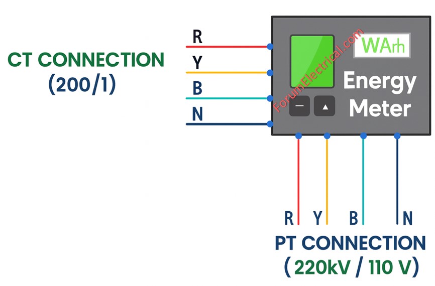
5). MF – Multiplying Factor (Metering Factor / Scaling Factor)
Multiplying Factor (MF) scales use internal measurements to correspond with actual primary values that is compensating for CT/PT ratios, measuring tap differences and minor measurement losses.
The MF (Multiplying Factor / Metering Factor) arrangement must meet the accuracy and scaling standards given in IEC 61869-1 & IEC 62053 series which encompass CT/PT ratio applications and relay metering accuracy classes.
Used For:
• Scaling CT/PT ratios
• Correcting metering display
• Matching relay internal calculations to actual system ratings
Example
If CT=400/5 but relay sees only 4A when actual is 5A:
Practical Notes
MF must be properly configured or else improper MF will result in incorrect displayed values & mislead engineers during testing and commissioning.
MF does not modify protection logic until the relay utilizes the scaled value to compute pickup which can verify that the pickup parameters follow the same scaling convention.
• MF = 5/4 = 1.25 (applied to correct reading)
In ABB/Siemens relays
MF helps adjust:
• Current display
• Voltage display
• Power/energy calculation
How these setting work together in a Relay?
When a fault occurs:
1). Relay measures current (CT secondary).
2). Calculates PSM using pickup setting.
3). Uses selected IDMT curve and finds base operating time.
4). Applies TSM to adjust final trip time.
5). If it’s earth fault, it uses EL setting instead of phase O/C.
6). Display and measurement corrected by MF.
Practical Example: Complete Relay Setting Coordination
Step 1: System Data
• CT: 300/5 A
• Load current: 200 A
• Fault current: 3000 A
• IDMT: Standard inverse Step 1: Pickup (PS) Pickup=1.5×5=7.5A
Step 2: PSM
PSM = 50A /7.5A = 6.67 A
Step 3: Relay Curve Time
From SI curve @ PSM=6.67 → 1.05 sec
Step 4: Apply TSM
Assume TSM = 0.2
Trip time = 0.2 x 1.05 = 0.21 seconds
Thus the relay will trip in 0.21 sec.