")
- What is a Relay?
- What is the principle of a Relay?
- Terminals of Relay
- Terminal Identification
- Operation of Relay
- Relay Coil Test
- Relay Datasheet
- How to Test a Relay?
- Preparing the Relay
- 1). Using Multimeter
- 2). Using Power Source (Battery)
- 3). Normally Closed (NC) Terminal Test
- 4). Normally Open (NO) Terminal Test
- What is a Solid State Relay?
- Why do use Solid State Relay (SSR)?
- How to Test a Solid State Relay (SSR)?
- 1). Testing the DC Controlled SSR Relay
- 2). Testing AC-Controlled SSR Relay
- 3). Testing Solid State Relays in Diode Test Mode (DMM)
- Standards followed in testing Relay
- Difference between Solid State Relay & Mechanical Relay
- Solid State Relay vs Mechanical Relay
- What is an example of a solid-state relay?
- What is the simplest way to test a relay?
- How can you check if a Relay is bad?
What is a Relay?
An electromechanical switch is called a relay. It energizes the coil in a circuit by applying a small amount of electricity. To adjust the switch position, the coil creates a magnetic field that forces a movable lever, or pole.
What is the principle of a Relay?
The relay operates on the basis that it will change the state of the control circuit and accomplish a certain control or protection goal when a given input quantity such as
- Voltage,
- Current,
- Temperature,
- Speed,
- Pressure, etc.
reaches a predefined value.
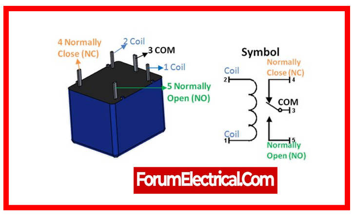
Terminals of Relay
Relays can feature four types of terminals:
- Coil,
- Common,
- Normally Open (NO), and
- Normally Closed (NC).
The coil (also known as the control input) connector is often connected to a low-power source that regulates the relay’s switching mechanism.
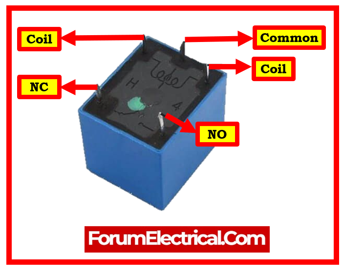
- 2 of them are coil input terminals, which are effectively the control input (activating and deactivating the relay).
- The common terminal serves as the high voltage circuit’s feeding input. The input passes through the relay’s pole (switch) to either the NO or NC terminal.
- When the relay is deactivated, the normally opened (NO) terminal remains connected to the common terminal. It closes once the relay is activated.
- The normally closed (NC) terminal is the relay’s other terminal, which remains connected to the common terminal until the relay is activated
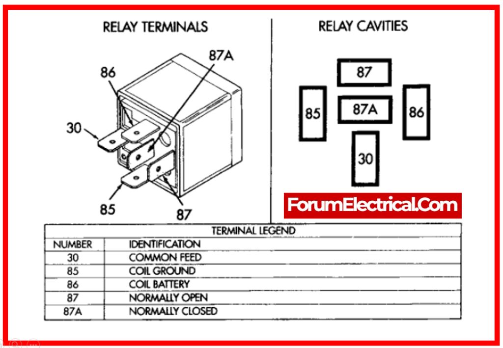
Terminal Identification
Generally, the terminals are stated on the relay’s protective cover. If there is no information regarding its terminals, you can identify it with an Ohmmeter.
Unless specified, the coil’s resistance is less than 400Ω. The coil terminals will be those with a resistance of roughly 300Ω.
When the relay is turned off, the resistance between the NC terminal and the common terminal is nearly zero.
When the relay is turned off, the resistance between the NO terminal and the common terminal becomes infinite.
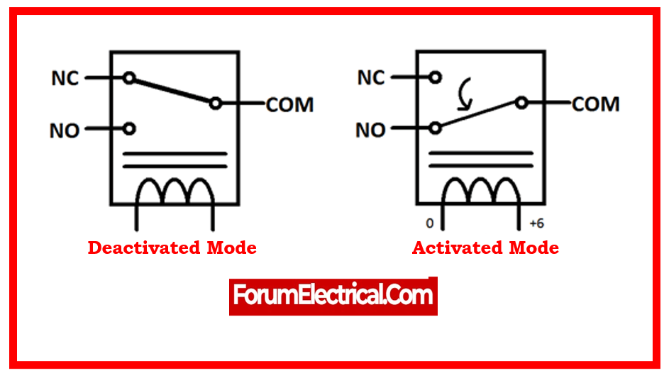
Operation of Relay
Deactivated mode: When no power source is attached to the coil input, the current flows from the Common terminal to the NC terminal.
Activated mode: When the coil is activated, current flows exclusively from the common terminal to the NO terminal.
Relay Coil Test
This test is used to determine the coil condition (open, closed, or shorted turns). This problem happens when the coil’s input voltage exceeds the specified value. The operating input parameter’s minimum and maximum values are defined in its datasheet.
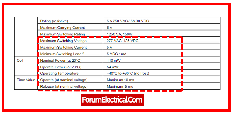
Relay Datasheet
How to Test a Relay?
Relays are individual components (as opposed to integrated circuits) that employ a low-power logic signal to operate a much higher-powered circuit. The relay separates the high-power circuit while also protecting the lower-power circuit via a small electromagnetic coil that the logic circuit may regulate. You can learn to test coil & solid-state relays.
Preparing the Relay
Check the relay visually. Numerous relays have a clear plastic casing with coil and connections. Damage like melting or blackening will assist identify the problem.
Modern relays include LEDs to indicate their status. Having control voltage to the relay (or) coil terminals (usually line and common) with that light off indicates a defective relay.
Disconnect power. All batteries & line voltage should be disconnected before electrical work. Capacitors can keep a charge for a long period after power is removed, so be careful. Never short capacitor terminals to discharge.
Relays have conventional pin arrangements, however check the manufacturer’s data sheets for pin counts. These are usually printed on relays.
Datasheets may contain current & voltage ratings, pin configurations, & other information that can assist you test and remove most mistakes. Testing pins at random without knowing their arrangement is possible, although relay damage may cause unexpected outcomes.
Relays of a certain size might additionally have this information printed on their outer enclosure.
Determine relay coil requirements. The relay enclosure should list the manufacturer’s part number.
Check the control coil data sheet for voltage and current requirements. Larger relay enclosures can also have this printed.
Test the control coil for diode protection. Noise spikes can harm logic circuitry, hence a diode surrounding the pole is typically utilized.
Drawings will represent the diode as a triangle with a bar in one corner. The bar will connect to the control coil’s positive input.
Check relay contact configuration. The data sheet or larger relays may print this. In designs, relays with one or more poles have a single line switch attached to a pin.
Each pole can have NO or NC contacts. These contacts will be drawn as relay pin connections.
The relay drawings show each pole touching the pin for NC contacts or not touching for NO contacts.
Check the relay contacts’ de-energization. Test the resistance across each relay pole and its NC and NO contacts with a DMM.
Each NC contact should read 0 ohms to its pole. To the pole, all NO connections should indicate infinite resistance.
Utilize an independent voltage source that matches the relay coil’s rating.
Make that independent voltage source is polarized if the relay coil is diode protected. Check for a relay click when powered.
Check relay contact energization. Test resistance between each relay pole and its NC and NO contacts with a DMM.
To the pole, all NC contacts must read infinite resistance. Zero ohms should be read on all NO connections to the pole.
1). Using Multimeter
Relay testing can be done in two multimeter modes:
- Continuity Test Mode
- Resistance Mode
Continuity Test Mode
The primary objective of this test is to ensure the coil’s continuity.
- Set the multimeter to continuity test mode.
- Connect multimeter probes on the coil terminals.
- If the multimeter beeps (or shows any indication of continuity), the coil is electric closed.
- If the multimeter does not beep, it means the coil is open and damaged. The relay should be changed.
- If meter lacks a continuity function (or) does not provide any indication of continuity, utilize the second mode.
Yet, utilizing this continuity mode to test a relay does not reveal any shorted coil turns.
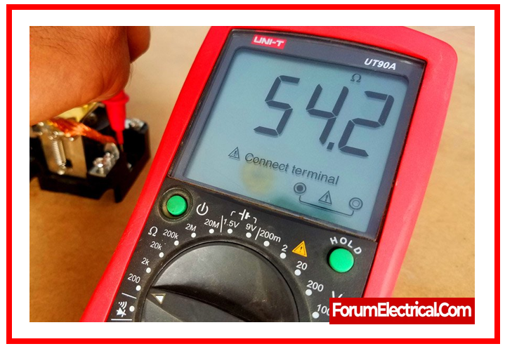
Resistance Mode
If want to test a relay with an Ohmmeter, you need perform some preliminary analysis.
The datasheet contains the nominal value of coil resistance. You can access its datasheet online by entering the model number found on its protective enclosure.
However, in most conditions, the coil’s resistance is less than 400 ohms.
- Set the multimeter to Ohmmeter mode.
- Place probes on both coil terminals.
- Record reading of resistance on the multimeter.
- If the measured resistance equals the resistance specified in the datasheet, the relay coil is acceptable.
If the resistance is very low (or) very high, the coil is most likely short-turned or open.
2). Using Power Source (Battery)
Precaution: Remember, you should not use this mode until you have the technical ability to operate a power source while taking the essential safety precautions.
- If the relay is still connected to a circuit, remove it.
- Locate the coil terminals.
- Connect the batteries to the coil terminals.
- If you hear a click sound immediately after connecting the coil terminals, the relay works.
- If it doesn’t click, the coil is open and damaged. The relay has to be replaced since the coil can’t be fixed.
3). Normally Closed (NC) Terminal Test
This relay test gives the necessary information for relay switching to make sure that the terminals connect and detach during coil energizing.
- The NC terminal remains closed unless the relay is activated.
- Set the multimeter to continuity mode.
- Set one probe on the NC terminal & the other on the relay’s common terminal.
- When the coil is de-energized (deactivated), the meter should indicate a continuity signal (beep).
- Now, activate the coil by connecting it to a power source, (or) manually push the lever (armature) with a finger or the test button (if it has one).
- If the gauge does not beep, it may be due to broken wires.
You can also test it utilizing an ohmmeter. A good relay has a 0 Ohm NC terminal resistance when deactivated and infinite resistance when triggered.
4). Normally Open (NO) Terminal Test
This test verifies the connection between the common terminal and the NO (normally open) terminal.
NO terminal is open unless the relay is activated.
- Set the multimeter to continuity mode.
- Insert the probes on both the NO and the common terminals.
- If the relay is deactivated, the meter does not beep or exhibit any signs of continuity.
- Now, turn on the relay or manually touch the contacts; the meter must beep to indicate continuity.
- If the meter does not indicate any continuity, relay conductors have been destroyed.
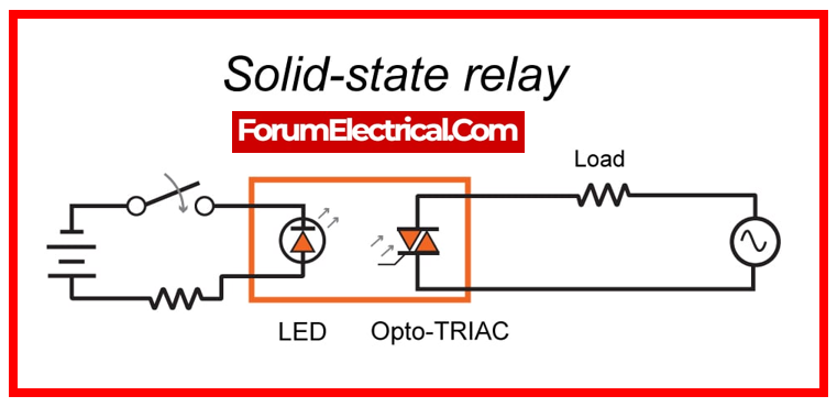
What is a Solid State Relay?
An electrical switching device known as a Solid State Relay (SSR) is activated or deactivated by applying an external voltage, either DC or AC, across its control terminals. Solid-state relay provides the same working as an electromechanical relay, but they last longer because they don’t have any moving parts.

Why do use Solid State Relay (SSR)?
Electrical loads can be controlled by solid-state relays, which are the semiconductor counterparts of electromechanical relays. Although the solid-state relay is a highly complicated device, its primary function when it is activated is to activate a single output load.
You can use Solid State Relays to connect your PLC output cards to the loads in the process.
Thyristors and TRIACs are more designed to drive resistive heating elements, therefore Solid-State Relays that use these electrical components in their output circuits are better appropriate for these applications.
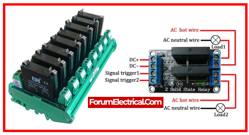
How to Test a Solid State Relay (SSR)?
1). Testing the DC Controlled SSR Relay
This is the simplest and most accurate way to test & troubleshoot an SSR (Solid State Relay).
To test a solid state relay, follow the instructions outlined below.
- Connect the 9V DC control voltage to the input, & connect a switch to the terminals “3” and “4”.
- Connect a 100W bulb to the load side with 110V (or) 220V AC at terminals “1” and “2”. To complete the circuit, connect the first terminal “1” of the relay to the bulb and AC power, and connect the second wire from the outlet to terminal “2”.
- Now, turn ON & OFF the “On/Off Switch”. If the light bulb turns on and off, the relay is in good condition; otherwise, the relay is damaged and needs to be replaced.
2). Testing AC-Controlled SSR Relay
The procedure for testing an AC Controlled Solid State Relay is the same as described before.
- However, you have to supply AC Control Voltage rather than DC.
- If the light bulb turns on when the switch is closed and “OFF” when the switch is opened. The relay works as expected; otherwise, the relay is faulty & should be replaced.
3). Testing Solid State Relays in Diode Test Mode (DMM)
To test a solid state relay using a digital multimeter, follow the instructions outlined below:
- Turn the knob of multimeter to the “Diode Test Mode”.
- Connect the A1(+) & A2(-) terminals to multimeter.
- If the relay is in good condition, the multimeter will show 0.7 (for silicon transistors) or 0.3 (for germanium transistors).
- If the multimeter displays “0” or “OL”, it indicates that the relay is destroyed and malfunctioning.
Standards followed in testing Relay
Relays must be tested to guarantee that they operate properly in a variety of electrical & electronic systems. Guidelines for testing relays are provided by many standards bodies. For the purpose of testing relays, including Solid State Relays (SSR) & Coil Relays, the following references from IEEE, IEC, and ANSI standards are provided:
- General standards for testing relays used in protective relay & control applications are outlined in IEEE C37.90. It covers test protocols and documentation, among other areas of relay testing.
- Relays and protective equipment testing are covered by this set of IEC (International Electrotechnical Commission) standards. IEC 60255 is divided into sections that address different facets of relay testing.
- Guidelines for evaluating protective relays in AC systems are provided by ANSI C37.90.1.
Difference between Solid State Relay & Mechanical Relay
Solid State Relay vs Mechanical Relay
| Parameters | Solid State Relay | Mechanical Relay |
| Operating Principle | Solid State Relays (SSRs) use semiconductor devices like thyristors (or) TRIACs to switch a load. They have no moving parts & rely on electrical components to isolate and switch. | Mechanical relays utilize physical contacts (often made of metal) which move to open (or) close the circuit. The movement is usually induced by an electromagnet. |
| Switching Speed | Solid State Relays (SSRs) feature higher switching speeds than mechanical relays. They can power on & off in microseconds, which makes them ideal for high-speed applications. | Mechanical relays have a partially modest switching speed, typically in the millisecond range. |
| Durability & Lifetime | Since SSRs do not contain moving parts, they have longer lived and are more durable. They are less susceptible to wear & tear. | Mechanical relays feature physical contacts that wear out over time because of mechanical movement, resulting in a lower lifespan than SSRs. |
| Noise & Arcing | Solid State Relays (SSRs) produce less electrical noise & are less susceptible to arcing because they lack physical contacts that might bounce (or) arc during switching. | Mechanical relays may generate electrical noise and cause arcing across the contacts upon switching, particularly at high voltages (or) currents. |
| Size & Weight | SSRs are typically smaller and lighter than mechanical relays, particularly in high-power applications. | Mechanical relays are larger & heavier because of the physical components needed for switching. |
| Reliability in Harsh Environment | SSRs tend to be more reliable in tough situations because they are less susceptible to vibration, shock, and pollution. | Mechanical relays can be more prone to problems in hostile environments because of their moving parts. |
| Cost | SSRs are typically more costly than mechanical relays, particularly in high-power applications. | Mechanical relays are often less expensive, particularly for low to moderate power requirements. |
What is an example of a solid-state relay?
Solid-state relays include the Sensata-Crydom Series 1 panel mount SSRs. These relays can be found in a wide range of current and voltage ranges (10 to 90 A at 24 to 530 V AC), which makes them appropriate for a variety of industrial applications, including motion, power, heating, and lighting control.
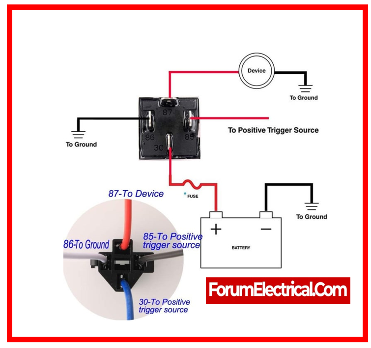
What is the simplest way to test a relay?
To test this, leave the multimeter set to ohms & measure the resistance across the switch pins. On a 4-pin relay, these are usually labeled 87 and 30. There should be no resistance at all in these pins. If you do, it means the pins have become stuck closed & the relay is malfunctioning.
How can you check if a Relay is bad?
You may also determine whether your relay is functioning properly by using your multimeter to measure resistance by switching it to the appropriate setting.
To carry out this procedure,
Step-1: You must first set your multimeter to the mode that measures ohms.
Step-2: Then you must connect the two leads to pins 85 & 86.
Step-3: The reading on a functional relay coil should to be between 50Ω & 120Ω, but in most cases, it is quite close to 75 ohms (75 Ω).