
Motor starting is one of the most major occurrences in electrical power systems.
When a large induction motor starts it may draw 5-8 times its rated current resulting in considerable voltage drops and system disruptions.
Understanding these dynamics is important for electrical engineers who design industrial buildings, power distribution systems & motor control applications.
This interactive simulation shows the entire motor starting procedure in a 132/11 kV power system allowing engineers and students to see real-time changes in current, voltage, speed and torque as the motor accelerates.
What happens during Motor Starting?
When an induction motor is activated many processes occur concurrently:
High Inrush Current
The motor initially performs similar to a short circuit drawing 6-7 times its full-load current.
The “starting current” rapidly drops as the motor speeds.
In our simulation you may see:
1). Initial current surge at time t=1 second (motor start)
2). Exponential decrease as the motor acquires speed.
3). Getting to steady-state current (about 0.1 pu)
Voltage Sag
The high starting current induces a voltage drop over the system impedance result in:
1). 11 kV bus experiences the most dramatic decline (may decrease to 75-85% of nominal).
2). 132 kV bus is also affected although to a lesser extent because to the stronger system strength.
3). Both voltages improve as the motor speeds and the current diminishes.
Speed Acceleration
The rotor does not accelerate to full speed immediately. It follows a distinctive curve.
1). Starts from 0% (standstill).
2). Gradually accelerates based on net torque
Net Torque = Electromagnetic Torque – Load Torque
3). Reach 100% (synchronous speed less slip)
4). Acceleration rate is used to determined by the motor inertia & load parameters.
Magnetic Torque
The torque produced by the motor fluctuates during the beginning process:
1). Maximum starting torque
2). Changes according to the square of the voltage & current
3). Affected by slip (difference between synchronous and rotor speeds).
4). Stabilizes once the motor has reached operational speed.
Parameters
Power (MW)
The rated power of motor that is being started. Larger motors cause more severe disturbances in electrical system.
Starting Current (PU)
Starting current (PU) expressed as “per unit” (pu) of motor’s rated current.
Typical range: 5.5 to 7.5 pu.
Smaller numbers indicate soft start or low voltage starting.
Larger levels indicate direct-on-line (DOL) starting.
Inertia Constant
Inertia constant specifies the mechanical inertia of motor & its connected load.
Higher inertia means slower acceleration.
Lower inertia means faster acceleration.
Typical range: 0.5 to 10 seconds.

How to use the Simulation?
Step-by-Step Procedure
Step-1: Set parameters by adjusting the motor power, starting current & inertia constant to meet the system requirements.
Step-2: Start the simulation. Click “Start” to start the step-by-step procedure of simulation monitoring the real-time changes in all parameters.
Step-4: Run the full simulation. Click “Run Full Simulation” to generate a full 8-second cycle explaining the entire starting procedure.
Step-5: Return to the start (intial) point to test different parameter combinations.
Observation
Stator Current Chart: Observe the tremendous initial spike & exponential decrease.
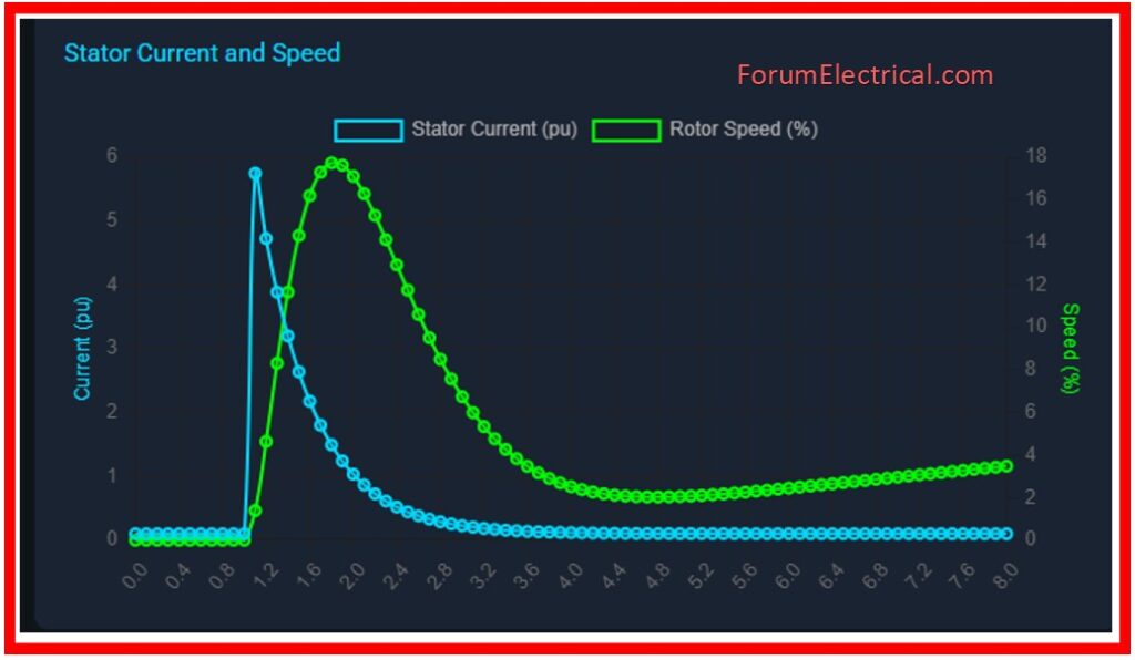
Rotor Speed Chart: Notice the S-curve acceleration pattern.
Voltage Chart: Observe the dip-and-recovery pattern at both voltage levels.
Torque Chart: Observe how electromagnetic torque varies with acceleration.
Results
This simulation will help you understand how motor starting influences power system voltage and the connection between current, speed & torque and the reason why starting current is significantly higher than running current.
Because system strength affects voltage stability.
Selecting the right motor starting method is important.
Simulation
Motor Starting Simulation
132/11 kV System Analysis
Stator Current and Speed
Voltage Profile
Electromagnetic Torque
System Details
System: 132/11 kV with Motor
Starting Method: Soft Start
Voltage Response: Dynamic Sag
Acceleration: Torque Based
Conclusion
Motor starting analysis is an essential aspect of the electrical system design with the direct implications for dependability, power quality & equipment life.
This simulation provides a simple visual method for analyzing complicated electrical and mechanical interactions during their key motor starting time.