
What is Slip in Motor?
The term “Slip in Motor” refers to the difference between the synchronous speed of the magnetic field (rotor speed) & the actual rotational speed of the rotor, specifically in the case of induction motors.
What is Slip?
Synchronous Speed (Ns)
This is the speed of the revolving magnetic field in the stator of the motor determined by
Ns = 120 x f / P
where
f is the power supply frequency (in Hz)
P is the motor’s number of poles.
Actual Speed (Nr)
The rotor’s real rotational speed.
Slips are defined as:
Slip (S) = Ns-Nr/Ns
Slip is generally stated as a ratio (or) percentage which is then multiplied by 100 to obtain a percentage.

Why Slip occurs?
Induction Principle
An induction motor’s rotor strives to match the rotating magnetic field’s speed but falls short due to the necessity for induced current.
This induced current generates a magnetic field that interacts with stator’s magnetic field providing torque while causing the rotor to lag behind.
Motor slip rises with load.
Under no load, the slip is negligible since there is no resistance to the rotor’s motion.
As the load increases so does the slip which provides greater torque to move the load.

Implications of Slip
Torque Generation
slip is required for torque generation.
Without slip, there should be no relative motion across the stator’s magnetic field & the rotor which means no induced current (or) torque.
Efficiency
Slip reflects the loss of energy in the form of heat caused by rotor resistance. Higher slip implies more energy is lost resulting in reduced motor efficiency.
Speed Control
Slip can be utilized for speed control purposes. The slip can be controlled by adjusting the voltage (or) frequency provided to the motor which in turn controls speed.
Types of Slip
1). Normal Slip
In regular operation, most induction motors have 2-5% slip at full load.
2). Locked Rotor Slip
When the rotor does not turn (for example, during starting or under extremely high load), the slip is 1 or 100%.
3). Negative Slip
Rarely identified, but theoretically feasible if external mechanical forces cause the rotor speed to surpass the synchronous speed.
Practical Considerations of Slip in Induction Motor
Motor Design
Various motor designs strive to reduce (or) optimize slip for certain purposes.
For Example: Squirrel cage motors may use varied rotor bar designs to control slip.
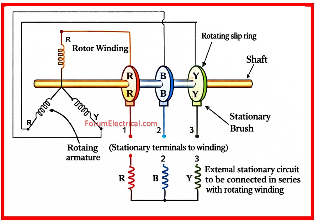
Slip Ring
In wound rotor motors, external resistors coupled via slip rings can control slip, affecting starting torque and speed.
Why does an Induction Motor never have Zero Slip?
Zero slip indicates that the rotor speed is identical to the synchronous speed.
If the rotor rotates at synchronous speed in the direction of the spinning magnetic field there will be no flux cutting action and no emf in the rotor conductors and no current in the rotor bar conductor and hence no generation of electromagnetic torque.
Thus, the rotor of a three-phase induction motor can never achieve synchronous speed.
Therefore slip is never zero in an induction motor.
Understanding slip is important for selecting, operating and maintaining induction motors particularly in applications requiring speed control, torque (or) efficiency.
