
The oil leak test is a most important quality assurance procedure performed on power transformers to verify their complete leak-proof integrity before commissioning.
- Objective
- Scope
- Test Pressure Requirements
- Safety Precautions
- Pre-Test Preparation
- Test Equipment Setup
- Valve Configuration
- Test Procedure
- Visual Inspection
- Step-1: System Setup
- Step-2: Baseline Measurements
- Step-3: Pressurization
- Step-4: 48-Hour Monitoring Period
- Step-5: Test Completion
- Observations
- High Risk Areas of Oil Leak
- Troubleshooting Common Issues
- Fault-1: Pressure Drop during Test
- Fault-2: Excessive Pressure Rise
- Fault-3: PRD Operation during Test
- Fault-4: Oil Ingress into Nitrogen Bag
- Results
- Summary
This test is essential because transformer oil serves multiple several functions as an
1). Insulating medium,
2). Coolant and
3). Arc-quenching agent.
Any oil leakage not only compromises the transformers performance and also affects the longevity of transformer but also possess environmental and electrical safety hazards.
This testing procedure simulates the worst case operating conditions by applying additional pressure to identify all potential weak points in welds, gasket joints, bushings and other sealed components before the transformer enters into service.
Objective
The primary objective of the oil leak testing procedure is to ensure that the transformer is completely leak proof under the simulated operational stress conditions.
Primarily, the test verifies that:
1). All welded joints are good & properly executed.
2). Gasket joints maintain their sealing integrity under pressure.
3). Mounted devices and accessories do not leak.
4). No oil ingress occurs into the oil-free compartments
The transformer can withstand pressure variations during continuous full load operation
Scope
During continuous full-load operation transformers experience thermal cycling that affects oil performance in several ways:
Temperature Rise
Oil temperature increases significantly reaching 60-90°C (or) higher.
Viscosity Reduction
Heated oil becomes less viscous and more fluid which allowing it to penetrate smaller gaps.
Thermal Expansion
Oil volume expands which leads to raising the level in the conservator and also increasing hydrostatic pressure.
Pressure Fluctuations
The breathing action of the conservator creates a cyclic pressure variations.
These conditions create the maximum stress on the sealing surfaces.
The oil leak testing shows the worst-case condition by applying additional pressure beyond the normal oil head.
If the transformer withstands this enhanced pressure for an extended period without leakage it provides confidence that leaks will not develop during normal service conditions.
Dry nitrogen (N₂) gas is the preferred pressurizing medium since it is:
1). Inert and non-reactive with transformer oil,
2). Non-combustible and safe,
3). Readily available & economical and
4). Easy to regulate and control.
Test Pressure Requirements
The testing procedure follows the established industry standards with specific pressure & duration requirements:
Test Pressure
The greater of the following shall be applied:
Normal pressure + 34 kN/m² (approximately 0.34 bar / 5 psi) at the top of the conservator
(or)
69 kN/m² (approximately 0.69 bar / 10 psi) at the bottom of the main tank.
Test Duration
48 hours of continuous pressurization
Acceptance Criteria
No oil leakage (or ingress into normally oil free spaces throughout the test period.
Important Note: It is recommended to conduct the test during maximum ambient temperature conditions. This allows for reduced applied pressure during the holding period as oil naturally expands and helping to prevent excessive pressure that could trigger Pressure Relief Device (PRD) operation.
Safety Precautions
Pressure Safety
- Never exceed PRD operating pressure,
- Utilize only the calibrated gauges,
- Ensure nitrogen cylinder is secured properly and
- Keep pressure regulators in good condition.
Personnel Safety
- Wear appropriate PPE (safety glasses, gloves),
- Ensure adequate ventilation when releasing nitrogen,
- Do not enter confined spaces alone and
- Keep fire extinguisher nearby (though nitrogen is inert).
Equipment Safety
- Do not over-tighten fittings,
- Check for nitrogen cylinder leaks,
- Ensure all personnel are aware test is in progress and
- Post warning signs around power transformer/distribution transformer
Environmental Safety
- Have spill containment ready in case of any leak,
- Dispose of any leaked oil properly and
- Prevent oil contamination of soil (or) water.
Pre-Test Preparation
A complete preparation is essential for the successful and perfect oil leak test.
The following checklist should be completed in pre-test preparation:
Equipment Normalization
1). Verify that the rubber bag (if provided) is properly installed and normalized.
2). Ensure that the Buchholz relay (rupture relay) is correctly positioned & that are functional.
3). Confirm OLTC (On-Load Tap Changer) & also main tank are properly equalized (if applicable).
Mechanical Integrity
1). Verify all bolts & nuts are fully tightened to the specified torque values.
2). Conduct torque verification using calibrated torque wrenches.
3). Ensure new gaskets are installed at all the joints during assembly.
4). Inspect all gasket surfaces for cleanliness and also proper seating.
Test Equipment Setup
1). Arrange nitrogen cylinder with functional pressure regulator.
2). Verify pressure gauge calibration status and validity.
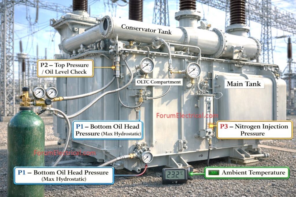
3). Install calibrated pressure gauges at 3 locations:
a). Bottom (P1),
b). Top of the main tank (P2) and
c). Applied (to apply) pressure line (P3)
4). Arrange accurate thermometer for an ambient temperature measurement.
5). Prepare oil temperature measurement device
Valve Configuration
1). Open valve between primary Buchholz relay and conservator.
2). Open valve between HV cable box (es) and conservator (if applicable).
3). Ensure that all radiator inlet and outlet valves are completely open.
4). Open valve between OLTC conservator and main conservator (if OLTC is provided).
5). Verify PRD operating pressure setting and functionality.
Test Procedure
Visual Inspection
1). Conduct thorough & complete the visual inspection for any oil traces anywhere on the transformer surface.
2). Ensure complete cleaning of the transformer external surfaces.
3). Clean surrounding area to easily detect any potential leakage.
4). Check all welding visually for defects (or) porosity.
Inspection Techniques:
1). Use strong lighting to detect oil film,
2). Check underside surfaces where oil might accumulate,
4). White paper (or) cloth test for minute seepage and
5). Mark the suspected areas and monitor them frequently
Step-1: System Setup
Carefully remove the OLTC breather and main tank breather from their mounting positions.
Connect the nitrogen cylinder output line in parallel to both the OLTC and main tank breather connection points to ensure that the simultaneous pressurization of all oil compartments.
Install Pressure Gauges
1) P1: Primary tank bottom (maximum hydrostatic pressure).
2) P2: Near conservator on top of primary tank (monitors highest pressure).
3). P3: Nitrogen supply line pressure monitoring.
Step-2: Baseline Measurements
Record Initial Pressures
1) Record the typical oil head pressure at P1 (bottom).
2). Note P2 pressure (top).
3). Calculate difference to check oil level.
Record Initial Temperatures
1). Ambient temperature using the calibrated thermometer.
2). Oil temperature (top oil temperature if accessible).
3). Record time and date of test commencement.
Step-3: Pressurization
1). Slowly open the nitrogen cylinder valve & also allow the regulated nitrogen to flow into the system.
2). Continuously monitor all 3 pressure gauges (P1, P2 & P3) as pressure increases.
3). Pressurize until the required test pressure is reached as:
a). P2 should show – Normal head pressure + 34 kN/m² (or)
b). P1 should show – 69 kN/m² (whichever is said to be greater)
4). Ensure that the pressure at tank top (P2) remains below (<) the PRD operating pressure with an adequate safety margin (typically 10 – 15% < PRD setting)
5). Fine-tune the nitrogen regulator to maintain the constant pressure.
Step-4: 48-Hour Monitoring Period
1). Every hour for the entire 48-hour duration record:
- Ambient temperature,
- Oil temperature (if measurable),
- Pressure at P1 (bottom),
- Pressure at P2 (top) &
- Applied pressure at P3
and keep on observations regarding leakage (or) abnormalities.
2). Conduct detailed visual inspections at regular intervals checking:
- All welded joints and seams,
- Gasket joints at covers, manholes and flanges,
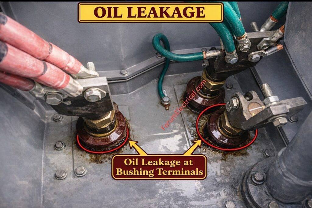
- Bushing mounting points,
- Valve glands and stems,
- Radiator connections,
- OLTC compartment (if applicable),
- Buchholz relay connections,
- PRD and pressure gauge connections &
- Cable box seals (if applicable)
3). As ambient temperature changes:
- If temperature rises it leads to oil expands and internal pressure may increase.
- If temperature drops it leads to oil contracts and pressure may decrease.
- Make minor adjustments to the nitrogen supply to maintain test pressure.
Leak Detection Methods
1). Visual inspection for oil traces (or) wetness,
2). Use clean white cloth to wipe the suspected areas,
3). Check for oil accumulation at all low points and
4). Monitor for oil mist (or) vapor.
Step-5: Test Completion
1). Continue checking (final inspection) all leak points.
2). Slowly release nitrogen pressure through controlled venting.
System Restoration
1). Disconnect nitrogen supply line.
2). Reinstall breathers (ensure proper silica gel condition).
3). Remove pressure gauges & seal openings.
4). Verify all the valves are in normal operating positions.
Observations
Systematic documentation is very essential to ensure the test validity, traceability and also future reference.
The following observations shall be recorded during the oil leak test.
Systematic documentation is crucial for test validity and future reference. The following parameters should be recorded:
CHECKLIST
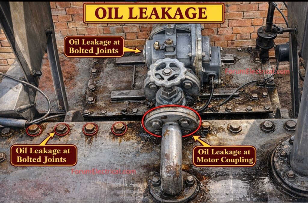
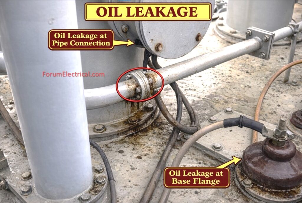
High Risk Areas of Oil Leak
Welded Joints
Especially at corners and complex geometries.
Gasket Joints
Cover plates, handhole covers & manhole covers.
Bushing Mounting Flanges
Particularly HV bushings with high mechanical stress.
Radiator Connections
Both at tank and radiator end.
Valve Glands
All valve stem packing areas.
OLTC Compartment
Seals between OLTC & main tank.
Buchholz Relay Connections
Both inlet & outlet flanges.
PRD Mounting
Gasket and thread connections.
Cable Boxes
Entry point seals and cover gaskets.
Conservator Base
Flange connection to main tank.
Troubleshooting Common Issues
Fault-1: Pressure Drop during Test
Causes
1). Nitrogen supply leakage.
2). Temperature drop causing oil contraction.
3). Actual oil leak from transformer.
Solutions
1). Check all nitrogen supply connections.
2). Verify ambient temperature changes.
3). Conduct thorough visual inspection.
4). Use leak detection fluid at suspect joints.
Fault-2: Excessive Pressure Rise
Causes
1). Ambient temperature increase.
2). Over-pressurization from nitrogen supply.
3). PRD malfunction.
Solutions
1). Reduce nitrogen input.
2). Release excess pressure carefully.
3). Monitor the PRD setting.
4). Wait for temperature stabilization.
Fault-3: PRD Operation during Test
Causes
1). Test pressure too close to the PRD setting.
2). Excessive temperature rise.
3). Faulty PRD.
Solutions
1). Immediately reduce pressure.
2). Check PRD setting.
3). Verify the temperature conditions.
4). Consider conducting test during cooler period.
Fault-4: Oil Ingress into Nitrogen Bag
Causes
1). Bag not properly normalized.
2). Excessive pressurization.
3). Bag damage (or) defect.
Solutions
1). Release pressure immediately.
2). Check bag installation.
3). Replace bag if gets damaged.
4). Re-normalize and restart test.
Results
Test Passed
The transformer passes the oil leak test if:
1). No visible oil leakage at any point during the 48-hour period.
2). No oil seepage detected on inspection cloths.
3). No oil ingress into normally oil-free spaces (nitrogen bag, cable boxes).
4). Pressure remains stable (accounting for temperature changes).
5).All gasket joints remain dry.
6). No oil accumulation at any low points
All valves, fittings and associated accessories shall then be restored to their normal operating positions.
A final thorough visual inspection shall be carried out to confirm that no oil leakage (or) abnormalities are present.
After satisfactory completion the commissioning process may proceed with the remaining scheduled tests.
All test records and supporting documents shall be properly archived and filed with the transformer commissioning documentation for future reference.
Test Failed
The test is considered failed if:
1). Any visible oil leakage occurs.
2). Oil traces appear on any of the surface.
3). Oil ingress occurs into oil-free compartments.
4). Continuous pressure drop indicates leakage.
5). Any joint shows wetness (or) seepage.
If the test fails all oil leak sources shall be accurately identified and clearly marked.
The severity of each leak shall be assessed to determine whether on-site repair is feasible or if major corrective action is required.
A remediation plan shall then be prepared based on the type of leak identified:
- Weld leaks may require re-welding followed by inspection and re-testing.
- Gasket leaks shall be rectified by replacing the defective gaskets and leaks from devices (or) fittings shall be addressed by repair or replacement as necessary.
Once repairs are completed all corrective actions shall be implemented under proper quality control supervision.
A full 48-hour oil leak test will be undertaken to confirm repair effectiveness.
The test report must detail remedial measures, observations and re-test findings for traceability and future reference.
Summary
Oil leak tests serve as essential quality assurance step-by-step method statements that verify power transformer mechanical integrity before service.
By verifying leak-free performance under elevated pressure it ensures proper assembly, sealing reliability, environmental safety and long-term operational confidence forming an important foundation for performance of reliable transformer service.