 for DC Power Systems: Step-by-Step Inspection Procedures")
Site Acceptance Testing (SAT) is essential for DC power system commissioning.
- Site Acceptance Testing (SAT)
- What is Site Acceptance Testing?
- Why SAT is essential for DC Systems?
- Safety and Compliance Standards
- Standards
- DC System Components
- 1). DC Charger/Rectifier
- 2). Distribution Panel
- 3). Battery Bank
- 4). Monitoring Systems
- DC Charger Inspection & Testing Procedures
- Initial Visual Inspection
- AC Supply Quality and Voltage Testing
- Output Voltage and Ripple Measurement
- Thermal Imaging & Temperature Monitoring
- Alarm Settings Verification
- Operating Mode and Function Testing
- DC Panel Inspection Essentials
- Nameplate and Rating Verification
- Physical Condition & Connection Integrity
- Bus Bar Testing
- Protection Device Verification
- Battery System Testing Procedures
- Initial Verification
- Physical & Connection Inspection
- Individual Cell Voltage Testing
- Total Bank Voltage & Temperature
- Impedance & Specific Gravity Testing
- Capacity and Discharge Testing
- Final Procedures
- Checklist
- Conclusion
For reliability, safety and regulatory compliance, DC system SAT procedures must be understood by those responsible for important infrastructure, data center operations (or) telecommunications networks.
This detailed DC power system SAT procedure covers the full procedure. We’ll show how to evaluate chargers, panels and batteries to assess technical data and develop successful testing procedures.
This post assists facility managers prepare for their first SAT, electrical engineers develop testing methods and maintenance technicians perform inspections.
Site Acceptance Testing (SAT)
What is Site Acceptance Testing?
Site Acceptance Testing is a systematic procedure conducted at the installation site to verify that equipment and systems meet design specifications, manufacturer requirements and applicable industry standards.
Unlike factory acceptance testing (FAT) which occurs at the manufacturers facility SAT takes place after installation and prior to operational commissioning.
Why SAT is essential for DC Systems?
DC power systems are different from AC systems in several important ways.
The direct current (DC) nature of these systems combined with battery backup capabilities makes them essential for applications where power interruption is not acceptable.
SAT ensures that:
• All components function correctly after the installation and integration.
• Grounding and bonding meet the safety requirements.
• Voltage and current parameters are within the acceptable ranges.
• Protection systems respond appropriately to the fault conditions.
• System documentation accurately reflects as the in-built configuration.
Safety and Compliance Standards
• Protect yourself with arc-rated clothes, safety glasses & insulated tools.
• Complete lockout/tagout (LOTO) protocols before starting work.
• Observe DC arc flash & short-circuit hazards which typically exceed AC system threats.
• Hydrogen from charging lead-acid batteries is explosive.
• Have good ventilation.
• Keep flames and sparks away from batteries.
• Check charger-to-system ground continuity.
• Verify grounding conductor gauge NEC compliance.
• Measure ground loop resistance (usually <0.1 ohm).
• Equipotentialize all metal structures.
Standards
DC system SAT should comply with the multiple standards and regulations:
• IEEE 1106
• IEEE 1188
• IEC 61427
• NFPA 70
• ANSI/IEEE C62.41
DC System Components
DC system components are
• DC Charger/Rectifier
• Distribution Panel
• Battery Bank
• Monitoring Systems
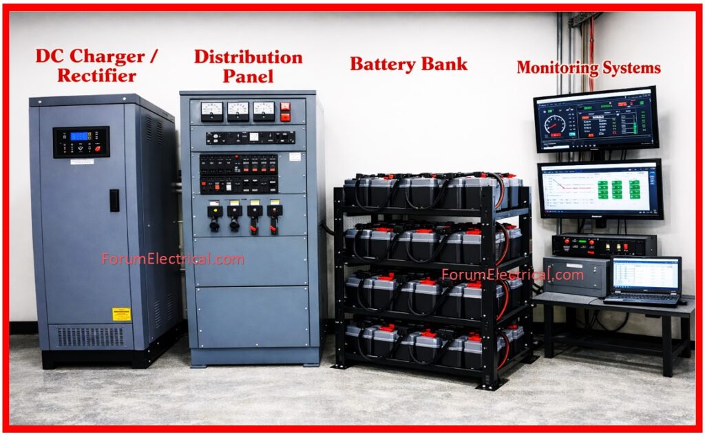
1). DC Charger/Rectifier
The charger converts AC input power to regulated DC output featuring:
• Three phase (or) single phase AC input capability.
• Voltage regulation within ±1-2% accuracy.
• Temperature compensated float voltage.
• Isolated ground construction for safety.
• Built-in overload and short circuit protection.
The charger is the primary power source requiring thorough testing to ensure a reliable operations.
2). Distribution Panel
The DC panel distributes power safely throughout the system which including:
• Bus bars for the current distribution.
• Protective devices (fuses, breakers or monitoring relays).
• Proper grounding provisions.
• Clear all connection labeling & circuit identification.
Panel failure can disable the entire system by making them detailed inspection essential.
3). Battery Bank
The battery system provides the emergency backup power and absorbs the load transients:
• Individual cells connected in series for the required system voltage.
• Lead-acid (or) lithium-based chemistry options.
• Terminal voltage monitoring the capability.
• Proper thermal management for good longevity.
Battery reliability directly impacts the system uptime during outages.
4). Monitoring Systems
Modern systems include:
• Distributed Control System (DCS) interfaces.
• Alarm and annunciation equipment.
• Temperature & voltage sensors.
• Real time (actual time) status monitoring.
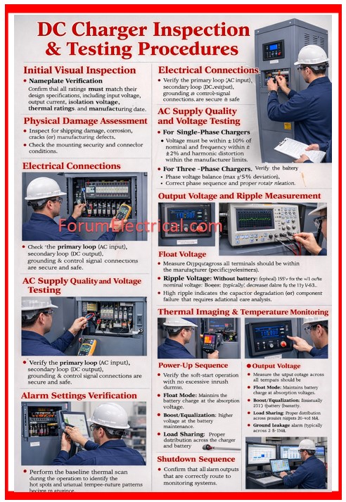
DC Charger Inspection & Testing Procedures
Initial Visual Inspection
Nameplate Verification
Confirm that all ratings must match their design specifications including input voltage, output current, isolation voltage, thermal ratings and manufacturing date.
Physical Damage Assessment
Inspect for shipping damage, corrosion, cracks (or) manufacturing defects.
Check the mounting security and connector conditions.
Electrical Connections
Verify the primary loop (AC input), secondary loop (DC output), grounding & control signal connections are secure and safe.
AC Supply Quality and Voltage Testing
Input power quality directly affects the charger performance.
For Single-Phase Chargers
Voltage must be within ±10% of nominal and frequency within ±2% and harmonic distortion within the manufacturer limits.
For Three-Phase Chargers
Verify phase voltage balance (maximum ±5% deviation), correct phase sequence and proper rotation direction.
Output Voltage and Ripple Measurement
Float Voltage
Measure the output voltage across all terminals should be within the manufacturer specifications (typically 109 – 120V for 110V systems).
Record the baseline values for any future comparison.
Ripple Voltage
This AC component must have a super imposed on DC output that indicates the charger health.
Excessive ripple may cause damage to the equipment & stress batteries.
Without battery: Peak-to-peak ripple should be < 3-5% of the nominal voltage.
With Battery: Ripple typically decreases due to the batteries filtering.
High ripple indicates the capacitor degradation (or) component failure that requires additional care analysis.
Thermal Imaging & Temperature Monitoring
Perform the baseline thermal scan during the operation to identify the hot spots and unusual temperature patterns (increase or decrease).
Check the power supply components, capacitors, heat sinks, output connections & transformer temperature.
Verify the charger float voltage by adjusting appropriately with the temperature changes.
Typical compensation is -2 to -4 mV/°C ensuring that the proper battery charging across the ambient temperature ranges.
Alarm Settings Verification
• Overvoltage alarm (typically 132V for the 110V system),
• Under voltage alarm (usually 88V),
• Overcurrent alarm at the rated capacity,
• Over temperature alarm (primarily 80-85°C) and
• Ground leakage alarm (typically across 2-5 mA).
Confirm that all alarm outputs that are correctly route to monitoring systems.
Operating Mode and Function Testing
Test all the chargers operational modes.
Power-Up Sequence
Verify the soft-start operation with no excessive inrush current.
Float Mode
Maintains the battery charge at the absorption voltage.
Boost/Equalization
Higher voltage for the battery maintenance.
Load Sharing
Proper distribution across the charger and battery.
Shutdown Sequence
Controlled shutdown without any of the transient overvoltage.
DC Panel Inspection Essentials
Nameplate and Rating Verification
Confirm the DC panel nameplate matches the design drawings with the correct voltage rating, primary bus bar current rating and also protection device specifications.
Physical Condition & Connection Integrity
Inspect for any physical damage, corrosion, arcing evidence (or) improper mounting.
Verify all connections are secure & tight with no discoloration indicating heat (thermal) damage.
Bus Bar Testing
Measure the resistance of primary current paths (typically <100 micro-ohms).
Inspect for any cracks in the insulators and verify all connection straps are secure and protected.
Protection Device Verification
Confirm that the protective devices are correct type and rating for application.
DC rated protection differs from the AC devices.
Test operation wherever possible and ensure the proper circuit labeling.
Battery System Testing Procedures
Initial Verification
Check nameplate information, verify manufacturing date (age affects performance), confirm the rated Amp-Hour capacity & validate chemistry type (lead-acid & lithium).
Physical & Connection Inspection
Inspect cells for any cracks, leaks (or) swelling.
Verify all the cells are properly secured.
Check cell terminals for corrosion and measure inter cell connection resistance (< 100 micro-ohms as per IEEE standards).
Individual Cell Voltage Testing
Pre Charge
All cells must read approximately 2.1V
During Charge
Monitor voltage rise (increase) rates and all cells should charge uniformly.
Post Charge
Stabilized the float voltage (primarily 2.20-2.23V per cell for lead-acid).
During Discharge
Monitor for any of the cell dropping faster than others.
Total Bank Voltage & Temperature
Measure voltage across entire battery bank; total should equal sum of individual cell voltages.
Monitor temperature at rest, during charging and during discharge.
Verify charger float voltage adjusts appropriately with the temperature changes.
Impedance & Specific Gravity Testing
Measure the AC impedance of each cell before and after commissioning.
For lead-acid batteries measure the specific gravity (fully charged: 1.200-1.300).
All the cells should have a similar values and significant variance that indicates the weak cells.
Capacity and Discharge Testing
Apply the rated discharge current while monitoring all cell voltages at the regular intervals.
Continue until the battery reaches the specified end voltage (typically 1.8V per cell).
Record the time to reach end voltage and also calculate the actual capacity that is delivered.
Final Procedures
Perform the boost charge while conducting the thermal imaging to identify the hot cells.
Verify charger battery voltage compatibility and also confirm charging current limiting is appropriate.
Checklist
Conclusion
Site Acceptance Testing is essential to the DC system safety and reliability.
From initial visual inspection to capacity testing the detailed procedures prevent defective equipment from entering service.
Proper SAT prevents costly issues (faults) later.
Site Acceptance Testing (SAT) quality is used to determines system reliability.
