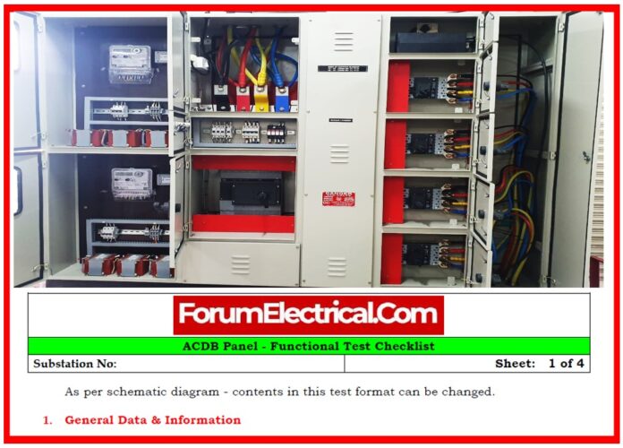
Electrical panels are the basis of power distribution systems, & their safe and efficient operation depends on extensive testing & inspection protocols.
This post describes a thorough approach to exploring control and protection panels, including
- Mechanical integrity,
- Functional inspections,
- Interlock systems, and
- DC and AC Auxiliary circuits.
These steps verify compliance with safety regulations & confirm readiness for operation before commissioning.
General Overview & Panel Information
Before starting any inspection (or) testing procedures, it is essential to document important information regarding the panel.
This comprises information like the serial number, type, manufacturer, voltage & current range, & the accompanying schematic drawing number.
It is also necessary to document the circuit reference according to the class specification.
These data points provide the foundation for traceability, quality assurance, & future maintenance requirements.
Mechanical Inspection & Visual Checks
A thorough mechanical inspection confirms the panel’s physical and structural integrity.
To avoid future problems or overheating, first ensure that all electrical & mechanical connections are properly fastened.
Check the panel for evident evidence of physical damage, wear, (or) manufacturing faults.
The panel’s overall condition should represent readiness for duty.
This involves cleaning, labeling, and ensuring that doors, knobs, & enclosures work properly. CT shorting must be examined to prevent any dangers during operation.
Furthermore, visual indicators & contact resistance on tripping & alarm circuits should be checked for good operation.
Ferrule markings must be cross-checked against specifications to guarantee correct circuit identification.
Each panel must be securely attached in its specified service area and inspected for proper earthing procedures.
Evaluate the panel’s structure and wiring to relevant specifications & standards, paying special emphasis to gasket sealing that prevents dust penetration.
All equipment nameplates must be examined to ensure they are consistent with approved designs and material lists.
Terminal connections on both internal & external wiring should be tight, well crimped, and free of sharp bends.
Ring-type terminals are suggested, particularly for current-carrying circuits, to guarantee strong connections.
Finally, check that all attached equipment is properly fastened and protected from shock or vibration.
Functional Verification of General Panel
Once the mechanical inspections are completed, proceed to verify the panel’s overall functionality.
Check the output from the AC outlets, the functionality of the illumination lamps, and the proper operation of the door-mounted limit switch.
The heater & thermostat circuits should be tested to ensure thermal stability within the panel.
All components within the panel must have legible and properly applied identification labels.
Manually spring charge the circuit breaker mechanism, then verify the manual open and close functions with the specified push buttons.
These tests guarantee that all important manual operations are responsive and in line with operational requirements.
Electrical Operation Assessment
Electrical operation testing determines the functionality of the panel’s automated components.
Start by examining the spring charging motor’s functionality when powered by electricity.
The circuit breaker must open and close properly using both local and remote control techniques.
As a precaution, the ability to trigger an emergency must be checked. Interlock functions, particularly those that inhibit dangerous operations, should be verified using the schematic representations.
Breaker status indicator lighting (ON, OFF, & TRIP) must be clear and constant. In addition, ensure that internal lighting, cubicle heaters, and all relays and contactors in the system work properly.
Interlock Logic Verification
Interlock testing ensures that the breaker logic performs as expected under variable voltage conditions across many busses.
Under typical circumstances, Bus 1 and Bus 2 should be closed, while the bus coupler remains open.
In the case of an overvoltage at Bus 1 or Bus 2, or both, the system must isolate the affected buses by changing the state of the breakers.
This testing demonstrates that the system can automatically respond to prevent backfeeding and ensure isolation during fault conditions.
DC Scheme Functional Check
The DC auxiliary circuit is crucial to ensuring reliable control and protection operations.
Start by testing the operation of DC tiny circuit breakers (MCBs).
All protective and auxiliary relays should be functionally checked to ensure they respond to simulated inputs.
Breaker operation, both open and closed, must be checked using devices labeled Q10x, Q10y, and Q10z.
All breakers should display proper status information, and spring charging via the DC motor should be validated.
Test the auxiliary power supply’s changeover capability as well as the auto/manual selector switch’s performance.
Final inspections should include checking the operation of breaker control switches and ensuring proper tripping for
- Overcurrent,
- Undervoltage, and
- Overvoltage conditions.
ACDB Auxiliary Circuit Inspection
The auxiliary circuits of the AC distribution board (ACDB) must be checked for completeness and compliance.
Record the circuit connections, cable sizes, and breaker ratings. Trace the route from source to destination circuits to ensure proper wiring.
To avoid misoperation, pay special attention to protective coordination and accurate segment labeling.
Annunciation & Alarm System Check
The annunciation system serves as the panel’s visual and audio alert mechanism.
Each input should be examined for proper LED color indication, which is commonly red or yellow depending on the type of alarm.
Audible buzzers should sound appropriately and reset when recognized.
Terminal block connections (Fmk TB No.) must be checked for proper wiring, and indication and alarm delays must be consistent with design specifications.
Ensure that the system generates warnings for both DC & AC auxiliary supply failures, & that these are properly displayed on the control panel.


