
An autotransformer may be described as an electrical transformer where there is only one winding either in series or in parallel.
- What is an Autotransformer?
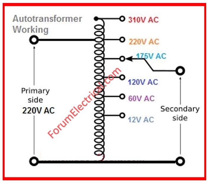
- Working Principle of Auto Transformer
- Construction of Auto Transformer
- Function of Auto Transformer
- Autotransformer on No-Load
- Autotransformer on Load
- Copper Savings in an Auto Transformer
- Advantages of Autotransformer
- Disadvantages of Autotransformer
- Applications of Autotransformer
- What is Variable Autotransformer?
What is an Autotransformer?
The term “auto” comes from the Greek In, which is for single coil alone (single = self) and not for programmed instruments.
An auto transformer is like a two-winding transformer but differs as to how the primary winding and secondary winding of the transformer are connected.
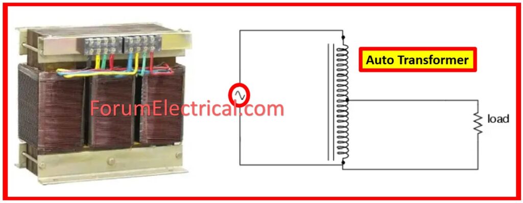
An autotransformer comprises one winding throughout where the tap is located between the primary winding and secondary windings.
The autotransformer, however, has the edge for one reason; the tap point can be adjusted to give the amount of voltage desired at the output.
But at the same time, the autotransformer has a major disadvantage: the secondary winding is not electrically separated from the primary winding.
On load condition a small amount of the load current is taken directly from the supply as a short circuit while the rest of it is taken through transformer action.
An Autotransformer is however used to regulate voltage.
Working Principle of Auto Transformer
The working principle of an autotransformer is on the basis of electromagnetic induction wherein a varying magnetic field generates voltage in a coil.
An autotransformer involves tapping a part of the winding as the primary winding while the rest part of the winding is also the secondary winding.
The voltage ratio of an autotransformer is therefore found by the number of turns in the primary coil divided with the turns on the secondary coil.
Construction of Auto Transformer
In a conventional transformer, primary and the secondary winding are electrically isolated while they are connected.
Unlike the ordinary Transformers, the primary and secondary windings in an auto Transformer are electrically connected to each other.
Auto transformers can be classified into two types according to their design.
In the first type, a continuous winding is used with taps placed at calculated positions in order to obtain the required secondary voltage.
On the other end, the second type has at least two separate coils which are electrically joined to form a continuous winding.
Function of Auto Transformer
From the winding AB which is tapped at C, hence the winding CB serves as an auxiliary winding.
The supply voltage is connected as marked across the AB and the load is connected as marked across the CB.
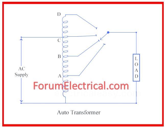
This tapping could be persistent, that is, they could be tapping more often at some times than at others.
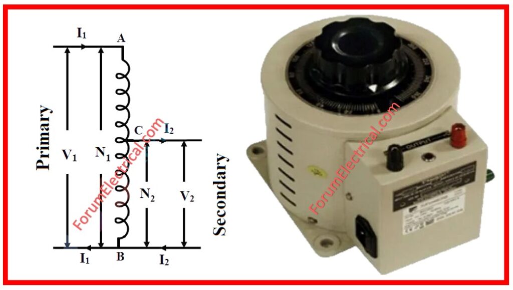
During the application of AC voltage V1 across AB, an alternating flux is created in the core, and therefore, an emf E1 is developed in the un-winding AB.
Some of this induced emf goes into the secondary side circuit.
Let,
V1 – Applied voltage at primary of the transformer.
V2 – Applied voltage at secondary of the transformer.
I1 – Primary Current
I2 – Load Current
N1 – Number of turns across A and B
N2 – Number of turns across C and B
Excluding no-load current, leakage reactance and losses,
V1 = E1
V2 = E2
Therefore, the transformation ratio:
K = V2/V1 = N2/N1 = I1/I2
Since, the secondary ampere-turns are in opposition to the primary ampere-turns, therefore, current I2 is in phase opposition to current I1. The voltage at the secondary side is some values below the voltage present at the primary side. Therefore current I2 is greater than the current I1. Thus the current I2 through section BC is equal to (I2 – I1).
Net ampere-turns for the section BC = current x turns
Due to the section BC, ampere turns
= (I1-I2) N2
= (I1/K-I1) x N1K
= I1N1 (1-K)
Let the above ampere turns be equation 1.
Due to the section AC, ampere turns
= I1 (N1-N2)
= I1N1 x (1-N2/ N1)
= I1N1 (1-K)
Let the above ampere turns be equation 2.
Equation (1) and (2) basically express the ampere-turns due to section BC and AC which cancel each other; this is however characteristic of the transformer action.
Autotransformer on No-Load
Type of connection of an unloaded autotransformer (step-down and step-up).
There the coil ‘AB’ is known as primary winding with N1 turns and coil ‘BC’ is known as secondary winding with N2 turns.
Here it can be observed that the primary and the secondary winding are coupled not only electrically but magnetically also.
Therefore, the power in the primary winding is transferred both magnetically and conductively to the secondary winding.
Autotransformer on Load
As stated earlier, a load is classified as connected to be loaded if it is connected to an autotransformer’s secondary.
The following figure illustrates the circuit connection of an autotransformer, associated with both the transformation of the voltage from high to low and vice versa.
Where, the current I1 is the current through the input of the transformer and the current I2 is the output current of the transformer or load current. The current in the common portion of the primary and secondary winding is the difference of the currents I1 and I2, whether the autotransformer is step down (or) step up.
In the case of the step down autotransformer the I2 > I1, so the current flowing through the common portion is
Current in common = I2-I1
In step-up autotransformer the current I2 < I1, therefore the current that flows through the common portion is
Current in common = I1-I2
Copper Savings in an Auto Transformer
Now let us discuss how much copper is saved in an auto transformer as compared to a standard two-winding transformer.
Any winding’s copper weight is evidently dependent on its length and cross-sectional area.
Similar to the previous case, the length of a conductor in a winding is inversely proportional to the magnitude of the turns it has, while the cross-sectional area depends with the rated current.
Therefore, weight of copper in winding is proportional to the result of number of turns and rated current of the winding.
Therefore, more the weight of copper in section AC is, more is its direct ratio with,
(N1-N2)I1
Also, weight of copper in the section BC proportional to
N2 (I2-I1)
Thus, total weight of copper in the winding of auto transformer varies in proportion with,
(N1-N2)I1 = N2 (I2-I1)
N1I1-N2I1+N2I2-N2I1
N1I1+N2I2-2N2I1
2N1I1-2N2I1
2(N1I1-N2I1)
Likewise, it can also be shown that the weight of the copper utilized in the two winding transformer is directly proportional to,
N1I1+N2I2
2N1I1
N1I1+N2I2
2N1I1 (in transformer N1I1=N2I2)
Quite simply,
Wa – Weight of copper in an auto transformer
Wtw – Weight of copper in a two winding transformer.
Wa/Wtw = (2N1I1-N2I1)/ 2(N1I1)
Wa/Wtw = N1I1-N2I1/N1I1
Wa/Wtw = (1-N2I1/N1I1)
Wa/Wtw = (1-N2/N1)
Wa/Wtw = 1-K
Wa = Wtw (1-K)
Wa = Wtw – K Wtw
Since the auto transformer uses less copper than the two winding transformer, it saves more copper.
Auto transformers use only one winding per phase and functions as against two particularly independent windings used in a standard transformer.
Advantages of Autotransformer
- An autotransformer has lesser core and copper losses than that of a 2-winding transformer; therefore it is more efficient.
- Autotransformer makes use of lesser conductor material as compared to the 2-winding transformer as explained in the previous steps.
- Lower voltage drops in both resistance and leakage reactance improve the voltage regulation.
- It is of smaller size and low in price as compared to a 2-winding transformer.
- It needs smaller excitation current than the fixed conventional excitation systems.
- An autotransformer works to generate a variable voltage.
Disadvantages of Autotransformer
- Technically, the primary side and the secondary side are directly related to each other. The load on the secondary side would receive full primary voltage when the common portion bread bc of the windings gets opened. This may harm the hardware associated with the secondary side.
- An autotransformer has reduced inside impedance than a 2-winding transformer hence allows a larger short circuit current.
- The autotransformer is not electrically isolated, in this way it cannot be utilized to electrically isolate two circuits
Applications of Autotransformer
- Through the use of autotransformers interconnection of power systems with different voltage levels is possible.
- The autotransformers with recordings are used to turn over enlistment engines and integrated engines.
- For conditions, where a sliding control in the voltage via an independent variable is needed, the autotransformers serve as the variac (Variable AC) transformers.
- It is employed as a starter to supply from 50 to 60 percent of full voltage to the stator of a squirrel cage induction engine during cranking.
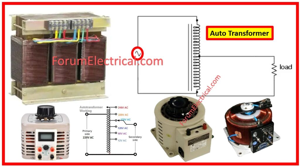
What is Variable Autotransformer?
Variable autotransformer (or) Variac is in a similar method as a fixed autotransformer.
The variable autotransformer is generally created with numerous main windings to deliver an adjusting second voltage that ranges from some volts to parts of a volt per turn.
This is made possible because the carbon brush or slider is constantly in contact with one or more of the turns of the primary winding.
An adhesive wound single primary coil, enclosed in a laminated magnetic core as in the auto transformer, is again employed but the secondary voltage is not fixed at some chosen tapping point as was the case with the auto transformer but could be tapped via a carbon brush.
Since the primary coil turns are also symmetrical along the length of the coil.
Then output voltage increases with respect to the angular rotation of the motor shaft or stator core.
This carbon brush is rotated or made to slide along an exposed part of the primary winding with the required supply voltage level to the winding.


