")
What is an Automatic Slip Regulator Starter (ASR Starter)?
An Automatic Slip Regulator Starter (ASR Starter) is a specialized device that regulates the starting and operating phases of slip ring induction motors.
These motors, which are frequently utilized in heavy-duty industrial applications, require controlled starting to reduce mechanical stress and electrical disturbances.
The ASR Starter enhances this process by controlling the slip (or) the difference between synchronous & actual speed, resulting in smooth acceleration and deceleration.
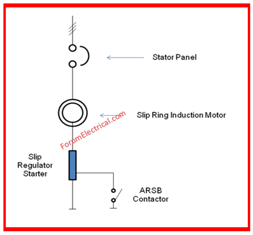
Components of an Automatic Slip Regulator Starter
Slip Ring Induction Motors: The main motor component requires slip adjustment.
Rotor resistors: External resistors are attached to the rotor circuit to regulate slide.
Contactor Relays: Electromechanical switches for connecting or disconnecting rotor resistors.
Control Units: To automate the operation, use a microcontroller or a PLC (programmable logic controller).
Current Sensors: To determine slip, measure the motor’s current.
Voltage Sensors: Monitor the voltage over the motor terminals.
Speed Sensors: Determine the motor’s speed for slip calculations.
Thyristors with SCRs (Silicon Controlled Rectifiers): Dynamically control the application of resistance using electronic devices.
Power Supply Units: Provides power to the control circuitry & sensors.
Cooling Systems: To dissipate heat produced by resistors & electronic components.
Display Panel: A user interface for monitoring & configuration.
Protective Devices: To keep the system safe, employ fuses, circuit breakers, & overload protection.
How an Automatic Slip Regulator Starter Works?
Initial Start: The motor starts with the highest rotor resistance to limit the starting current.
Current Measurement: When the motor starts, current sensors monitor the rotor current.
Slip Calculation: Speed sensors provide real-time data on rotor speed, & slip is determined as the difference between synchronous and rotor speeds.
Resistance Adjustment: Based on the slip & current measurements, the control unit modifies the rotor resistance by switching contactors or modulating thyristors.
Gradual Reduction of Resistance: As the motor powers up, the resistance steadily decreases, allowing for smoother acceleration and less slide.
Steady-State Operation: Once the motor attain near-synchronous speed, the rotor resistance is reduced and the motor operates at peak efficiency.
Dynamic Adjustment: During load fluctuations, the control unit dynamically adjusts the rotor resistance to maintain the correct slip while avoiding stalling or overloading.
Slip Calculation of an ASR Starter
The Slip regulator is constructed so that its resistance varies with frequency. When the motor starts at zero speed, the rotor frequency equals the supply frequency, & the slip regulator resistance is at its highest. And while running, the rotor frequency is low (based on slip) & the slip regulator resistance is low.
The value is determined as follows
RSR = R0 + Arfr
Where
RSR – Slip Regulator Resistance at any Frequency (SR).
R0 – Residual Slip Regulator’s DC resistance, which is normally around 3%.
A – Resistance Amplification Factor
f – Rotor Frequency
When the motor operates at higher speeds, the rotor frequency is low (usually 3-4%), and the slip regulator resistance is minimal.
The slip ring motor’s rotor voltage is determined by the equation shown below.
VR = s x RVss
Where
VR – Rotor Voltage at slip s
s -slip per unit.
RVss – Rotor Voltage at stationary
When running, the motor slip increases in proportion to the load, as does the rotor voltage.
To enhance motor torque and avoid current kicks, increase the running resistance.
RRS/Ph = [(RVss/1.73) / (RA x p.u. torque)]
R RS/Ph represents the equivalent star resistance of a slip regulator (In Ω).
RVss refers to the rated voltage of the rotor line at stationary.
1.73 represents the line-to-phase conversion factor.
RA refers to the rated rotor current (amps).
p.u.Torque refers to the intended motor torque at stationary per unit value.
The slip regulator resistance varies automatically and step-less as the motor speed (rotor frequency) changes.
Range: 37 KW/415 V to 6,000 KW (3.3, 6.6, and 11 KV).
Features of ASR Starter
Smooth Start
The ASR Starter gradually increases the motor speed, decreasing the early inrush current & mechanical shock. This smooth start extends the life of both the motor & its associated mechanical systems.
Slip Regulation
The ASR Starter precisely controls the slip by altering the resistance in the rotor circuit, resulting in optimal torque production & efficient motor performance during start-up & under varying loads.
Reduced Electrical Stress
Controlled starting current eliminates voltage dips and reduces pressure on the electrical network, making sure other equipment linked to the same power source runs smoothly.
Enhanced Protection
ASR Starters have protective characteristics such as
- Overcurrent protection,
- Thermal overload protection, &
- Phase failure protection
to protect the motor and starter from damage.
Energy Efficiency
The ASR Starter improves energy efficiency and lowers costs in industrial operations by improving the beginning process and eliminating losses associated with high starting currents.
Advantages of ASR Starter
- Provides controlled acceleration and deceleration, reducing wear on motor components.
- Operational Reliability: Maintains consistent motor operation under varying load conditions.
- Reduces energy usage by optimizing motor start-up & operation.
- Prevents mechanical & electrical stress during start-up, reducing the need for maintenance.
Applications of ASR Starter
Automatic Slip Regulator Starters are commonly utilized in industries wherein slip ring induction motors are popular, including:
- In mining, it is used for heavy-duty conveyors, crushers, & mills.
- In cement industry it is used for ball mills, crushers, & kiln drives.
- Used for rolling mills, crushers, & hoists in steel companies.
- Pumps, fans, and compressors for power plants & water treatment facilities.
You can also follow us on AutomationForum.co, Facebook and Linkedin to receive daily Instrumentation updates.
You can also follow us on ForumElectrical.com, Facebook and Linkedin to receive daily Electrical updates.


