
What is an Autotransformer?
There is a type of electrical transformer known as an auto transformer, which is also known as an autotransformer, which consists of a single winding that performs the functions of both a primary winding & a secondary winding.
There is a type of transformer known as an auto transformer, which is characterized by the utilization of a single winding to regulate the voltage level between its input and output terminals.
It has only one winding, which serves as both the primary & secondary winding of the transformer.
In a normal transformer, the primary & secondary windings are electrically distinct yet magnetically coupled.
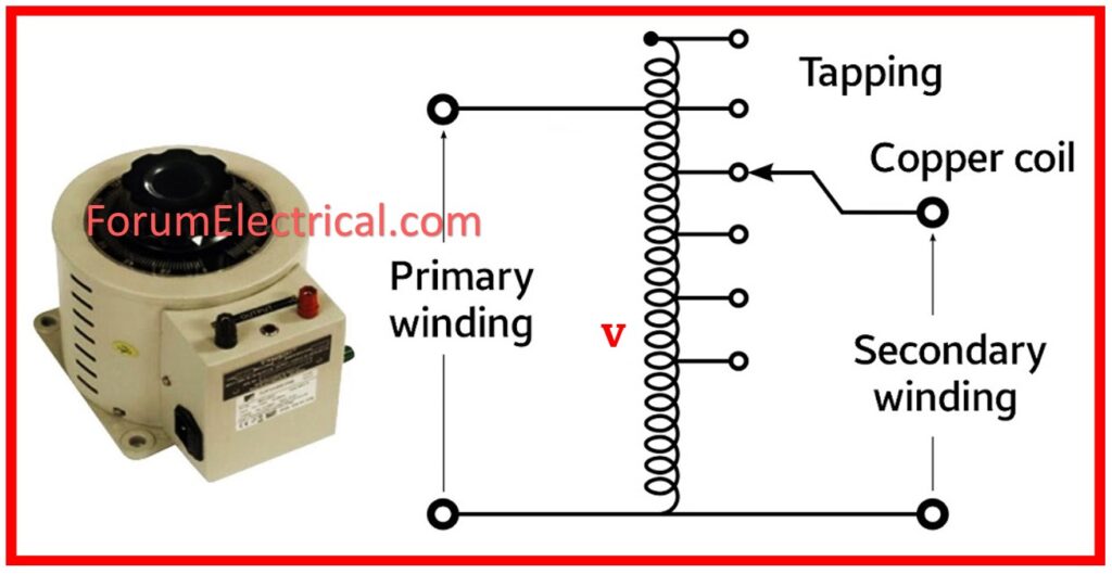
A portion of a single, continuous winding, in particular, fulfills two functions as of both the primary & secondary.
Autotransformer Turns Ratio Test
Purpose
An essential electrical test for autotransformers, the Turns Ratio Test (TTR) test is meant to evaluate the accuracy of turns ratio across the primary and secondary windings. This test is also known as the TTR test.
Scope
With the use of this test, potential problems such as
- Shorted Turns,
- Open Circuits, or
- Inaccurate Winding Connections
can be identified.
These faults have the potential to significantly impair the performance and safety of the transformer.
Test Procedure
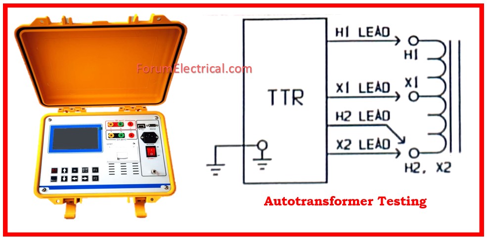
Step-1: Make sure that the transformer is de-energized and appropriately grounded.
Step-2: Make use of the proper precautions for safety, such as safety glasses & insulated gloves.
Step-3: Ensure that all essential safety procedures are followed, as described in the instructions provided by the manufacturer and the local safety regulations.
Step-4: Connect a suitable voltage source, which is normally low voltage AC, to one winding, which is typically the primary winding. This is the second step in the process.
Step-5: To determine the voltage that is present across the primary winding, it is necessary to connect a high-precision voltmeter.
Step-6: Then connect an additional high-precision voltmeter in order to determine the voltage that is present across the secondary winding.
Step-7: Apply the test voltage to primary winding for the purpose of determining the voltage.
Step-8: Record the voltages of both the primary & secondary sources.
Step-9: To calculate the turns ratio, divide the secondary voltage by primary voltage.
Step-10: The observed turns ratio will be provided to you as a result of this test.
Nameplate Data Comparison
Please make a comparison between the turns ratio that has been measured and the intended turns ratio that is provided on the transformer’s nameplate.
It is important to ensure that the measured value is within a defined tolerance range, which is normally ±0.5%.
Results
Accurate Turns Ratio:
Within the tolerance range, if the turns ratio that was measured is the same as the value that is shown on the transformer’s nameplate, this shows that the windings of the transformer are in good condition and that the connections are accurate.
Deviations
Shorted Turns:
A turns ratio that is lower than what was anticipated can be an indication that there are fewer turns than expected within a winding.
Open Circuits:
The presence of an open circuit in a winding can be indicated by a turns ratio that is of a higher value than what was anticipated.
Significant deviations from the predicted value may reveal faulty winding connections.
What is the Transformation Ratio in an Auto Transformer?
The transformation ratio is the ratio of secondary voltage to primary voltage, which is equal to the ratio of number of turns in secondary winding to number of turns in primary winding.
K = N2/N1 = V2/V1= I1/I2
Why is Short-Circuit Current higher in an Autotransformer?
The two winding transformer has electrical isolation. That is, there is no electrical short across the primary and secondary windings in an auto transformer.
Ex: Assume a 10 KVA transformer rated at 2300/230 V, with a leakage impedance of around 4%. If it is attached as an auto transformer and steps down from say 2530 to 2300 V which equates to a transformation ratio of 1.1 (2530/2300=1.1),
the impedance decrease will be:
4 X (0.1/1.1)= 0.364%
It has a leakage impedance of 9.1% of that of a two-winding transformer.
As a result, short circuit current in an auto transformer is higher than in a two-winding transformer, and a current limiting device is used to safeguard the auto transformer from the dangers of high short circuit current levels.


