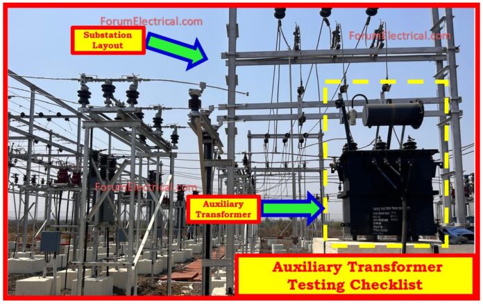
Auxiliary transformers play an important role in providing power to substation auxiliaries, and proper testing is required prior to commissioning.
- Nameplate Details Verification
- Mechanical and Visual Inspection
- Insulation Resistance & Polarization Index Test
- Winding Resistance Test
- Magnetization Current Measurement
- Vector Group Verification
- Calibration for Oil Temperature Indicators
- Voltage Ratio Test
- Insulating Oil Dielectric Strength Test
- Checklist
- Conclusion
This checklist outlines the standard testing procedures and inspections carried out to ensure the transformer’s health, performance, and compliance with design specifications.
Nameplate Details Verification
The first procedure involves verifying the auxiliary transformer’s nameplate data against the technical standards.
Key characteristics such as manufacture, power capacity, voltage rating, vector group (e.g., Dyn11), impedance % at nominal tap, primary & secondary current ratings, frequency (50 Hz), & available tap numbers are checked and recorded.
Ensuring accuracy at this step is essential for evaluating auxiliary transformer compatibility for the planned application.
Mechanical and Visual Inspection
A thorough visual inspection is conducted to detect any physical damage, external defects, (or) oil leaks.
The nameplate data is verified with the specifications given. Additional tests include the quality of the earthing system, painting, wheel stopper, cable terminations, & tightness of all exterior bolts.
The positions & indications of the off-load tap changer are verified for correctness. All control devices, protection relays, & accessories are checked to confirm proper labeling as per the approved drawings.
Insulation Resistance & Polarization Index Test
Utilizing a 5 kV insulation tester (megger), the insulation resistance is measured between HV-LV, HV-Earth, & LV-Earth. Readings are recorded at multiple time intervals, typically from 30 seconds up to 10 minutes.
The Polarization Index (PI) is calculated by taking the ratio of the 10-minute reading to the 1-minute reading.
A high PI value usually indicates excellent insulation health, while low values may indicate moisture infiltration or insulation breakdown.
Winding Resistance Test
A accurate micro-ohmmeter is used to evaluate winding resistance for both high voltage and low voltage windings.
The resistance is measured between phases (R-Y, Y-B, B-R) on the HV side & from each phase to neutral (r-n, y-n, b-n) on the LV side.
Measurements are corrected to 75°C using the standard temperature correction formula and compared to factory test values.
Consistent resistance values throughout phases suggest a uniform winding design, but large variances may indicate faults like as shorted turns or inadequate connections.
Magnetization Current Measurement
To examine the core condition, magnetizing current is measured by delivering a three-phase voltage to the HV winding while maintaining the LV winding open.
The current drawn at each phase (R, Y, B) is noted.
Low & balanced values suggest a healthy core with no short laminations, but larger or unbalanced values may signal core concerns.
Vector Group Verification
The auxiliary transformer’s vector group is verified by applying a 3-phase balanced voltage to the HV side & measuring the resulting secondary side voltages.
This test confirms that the phase displacement & polarity match the supplied vector group (e.g., Dyn11).
Any mismatch can results in phase shift difficulties in the system & demands rapid adjustment.
Calibration for Oil Temperature Indicators
To make sure accurate thermal protection, the Oil Temperature Indicator (OTI) is calibrated with a standard thermometer.
A variety of temperatures is applied, and the OTI values are compared with standard instrument.
Consistent readings indicate that the sensor is operating well, however variations may need sensor recalibration (or) replacement.
Voltage Ratio Test
The voltage ratio between the primary & secondary windings is evaluated across all tap locations to validate auxiliary transformer tap changer accuracy.
The measured secondary voltage is compared with estimated theoretical ratio, and the percentage error is computed for each phase.
This test checks the proper voltage transformation under various tap settings and assures consistent functioning.
Insulating Oil Dielectric Strength Test
A dielectric breakdown voltage test in accordance with IEC 156 is used to examine the quality of insulating oils.
The oil sample is tested utilizing a standard gap of 2.5 mm, & repeated breakdown voltage values are collected.
The average value is checked against the permitted minimum (typically 40 kV for transformers up to 36 kV). Low levels suggest contamination or moisture, necessitating oil filtering or replacement.
Checklist
Conclusion
The auxiliary transformer’s suitability for commissioning is validated by systematic testing and inspections.
Adherence to these procedures promotes safe operation, reduces the danger of premature failure, and ensures dependable power supply to important substation equipment.


